This online exhibit is based on the exhibit of the same name that was on display at the Albert H. Nahmad Panama Canal Gallery from April 21, 2023, to March 29, 2024. Unless otherwise noted, all items are from the Panama Canal Museum Collection, Special & Area Studies Collections, George A. Smathers Libraries, University of Florida.
Image from Garlington Family Photographs, c. 1913. II.2022.5.5
The Canal that cuts across the Isthmus of Panama is a testament to the audacity of its creators. From the engineers to those hand-digging dirt with shovels, each were essential, and each are worthy of recognition. But this exhibit is not about the who – it is about the how.
How, in 10 years, the United States:
moved more than 240 million cubic yards of material
designed and poured the most voluminous concrete structure of the modern world
reconstructed a trans-continental railroad
and created the largest artificial lake of its time.
As built, the Panama Canal is an extraordinary achievement that would have been impossible to create just a few decades earlier. Recent advancements and innovations in concrete, dredging, electricity, equipment, engines, dynamite, railroads, and many others, meant the difference between success and failure. Individuals and industries capitalized on these improvements and invented other solutions needed to complete an awe-inspiring engineering project in a time frame that pushed the limits of possibility.
The desire to employ new technologies to maximize the Canal’s use and efficiency continues today. In 2016, the Republic of Panama successfully expanded the Canal’s capacity to accommodate even larger ships.
In the summer of 1904, a small group of U.S. engineers arrived in Colón, Panama, to survey what remained of the French effort to dig a canal and to gather data for the monumental undertaking ahead. Before construction could fully begin, the U.S. had to decide what type of canal would work best in the location.
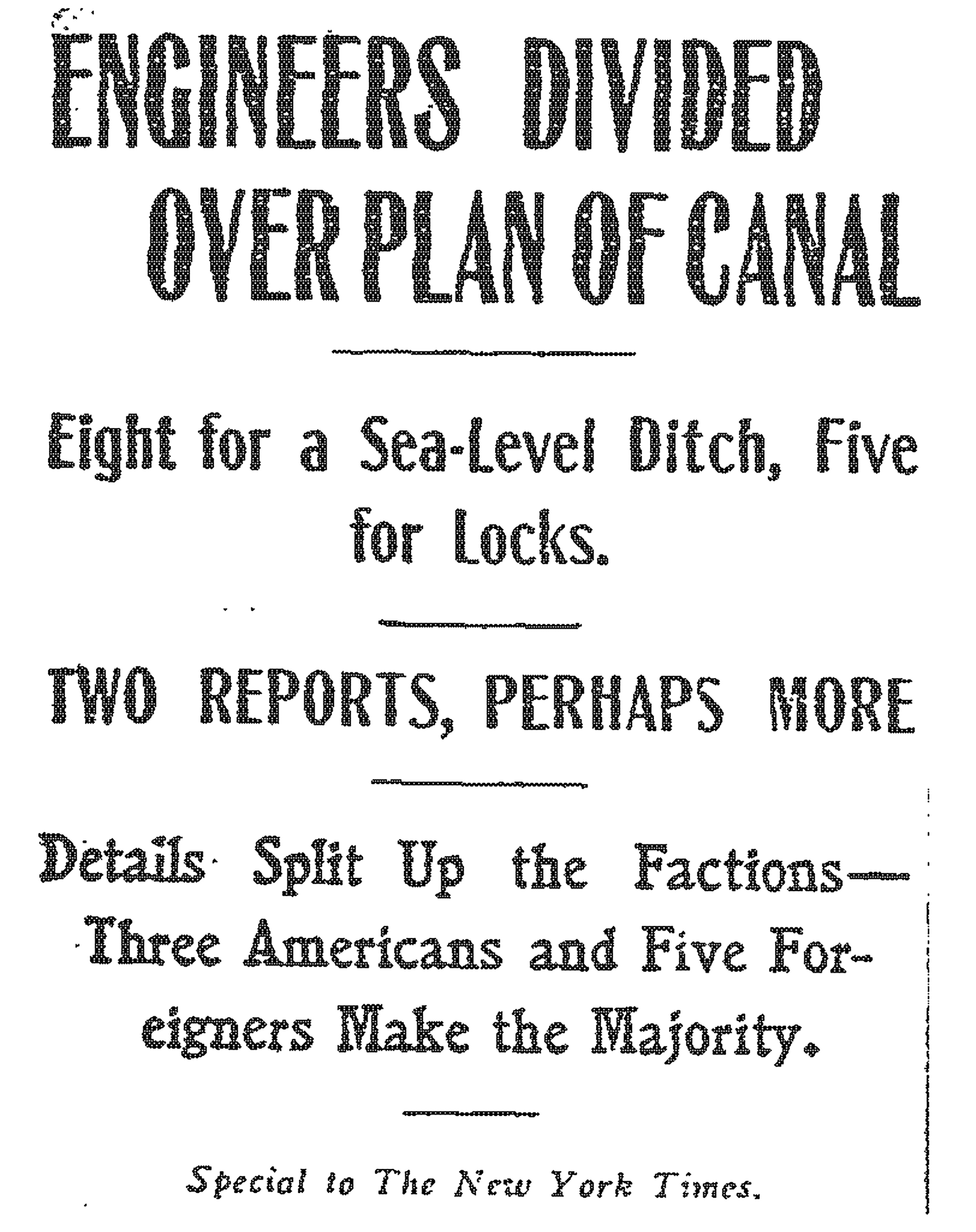
Engineers conducted extensive studies on whether to build a sea-level canal that maintained one elevation across the entire Isthmus or a lock canal. A lock canal would allow elevation changes, similar to a staircase going up and down. Battles around the decision played out in newspapers and even on the floor of the U.S. Congress. On June 29, 1906, the U.S. Senate voted to build a lock canal.
New York Times, February 27, 1905.
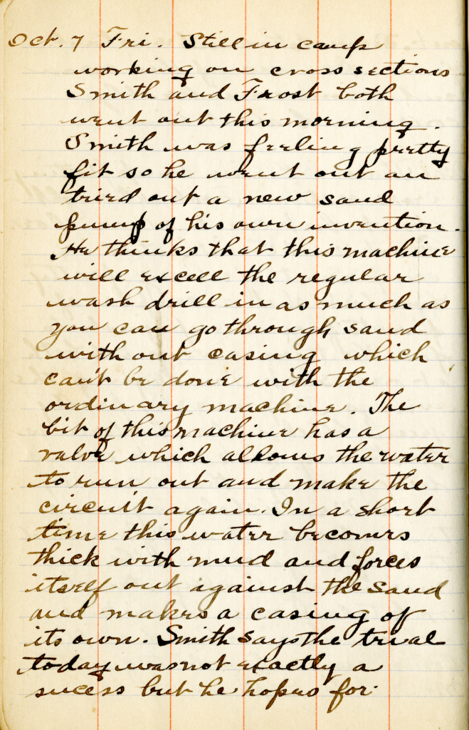
Move arrow below to view the diary page transcript.
Diary of Fred Lyon, c.1906. II.2022.48.1. Gift of the Sturges Family.
Photo Album of Fred Lyon, c.1906. II.2022.48.2. Gift of the Sturges Family.
Fred Lyon worked as a rodman (person in charge of transporting and setting up survey equipment) in one of the early groups. He and the others in his team often lived in a make-shift camp in the jungle near Gatun. There they cleared vegetation, took depth measurements of the river, surveyed the area, and sketched contours.
Surveying Transit, c.1899. II.2021.36.101. Gift of Brad Wilde.
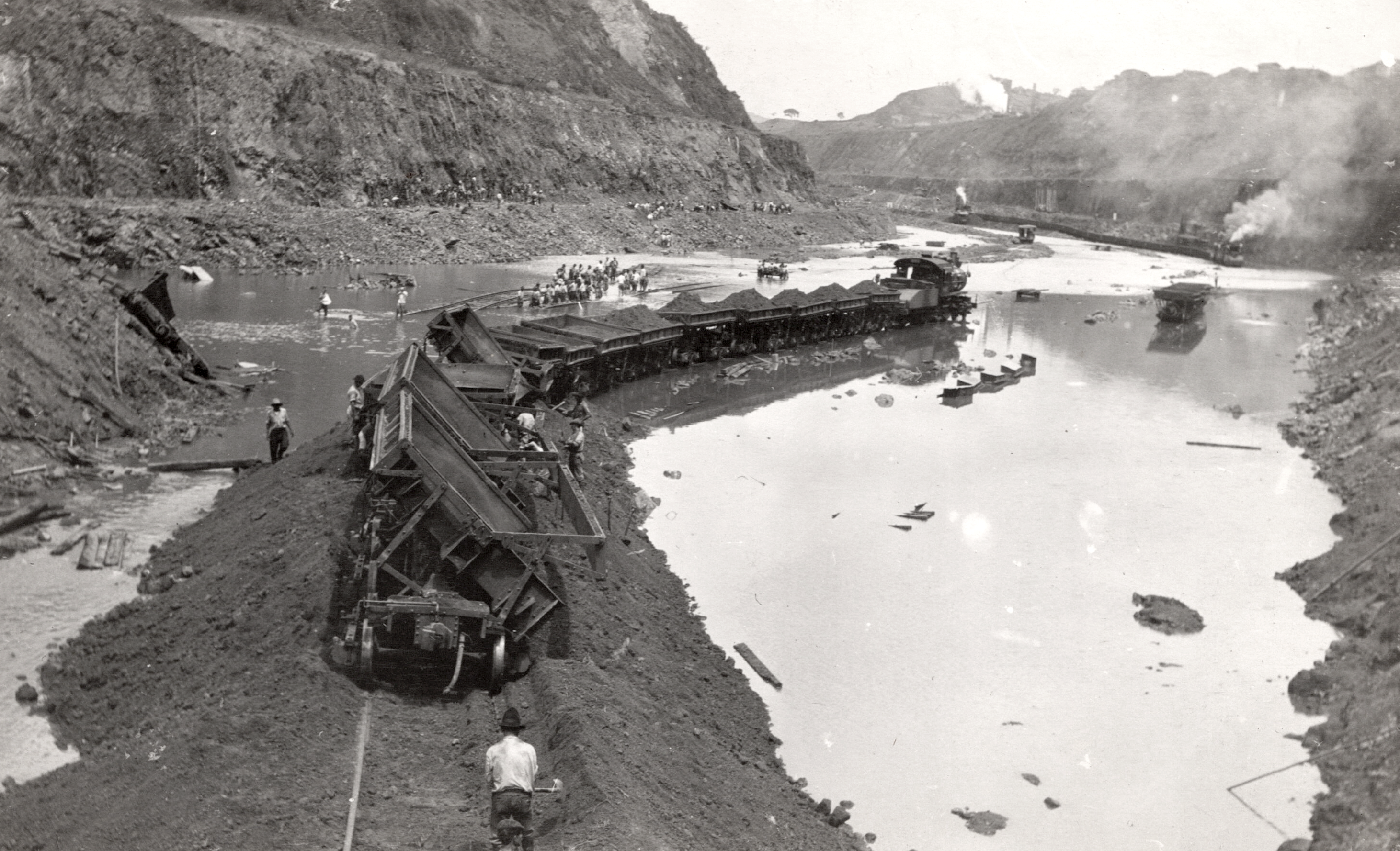
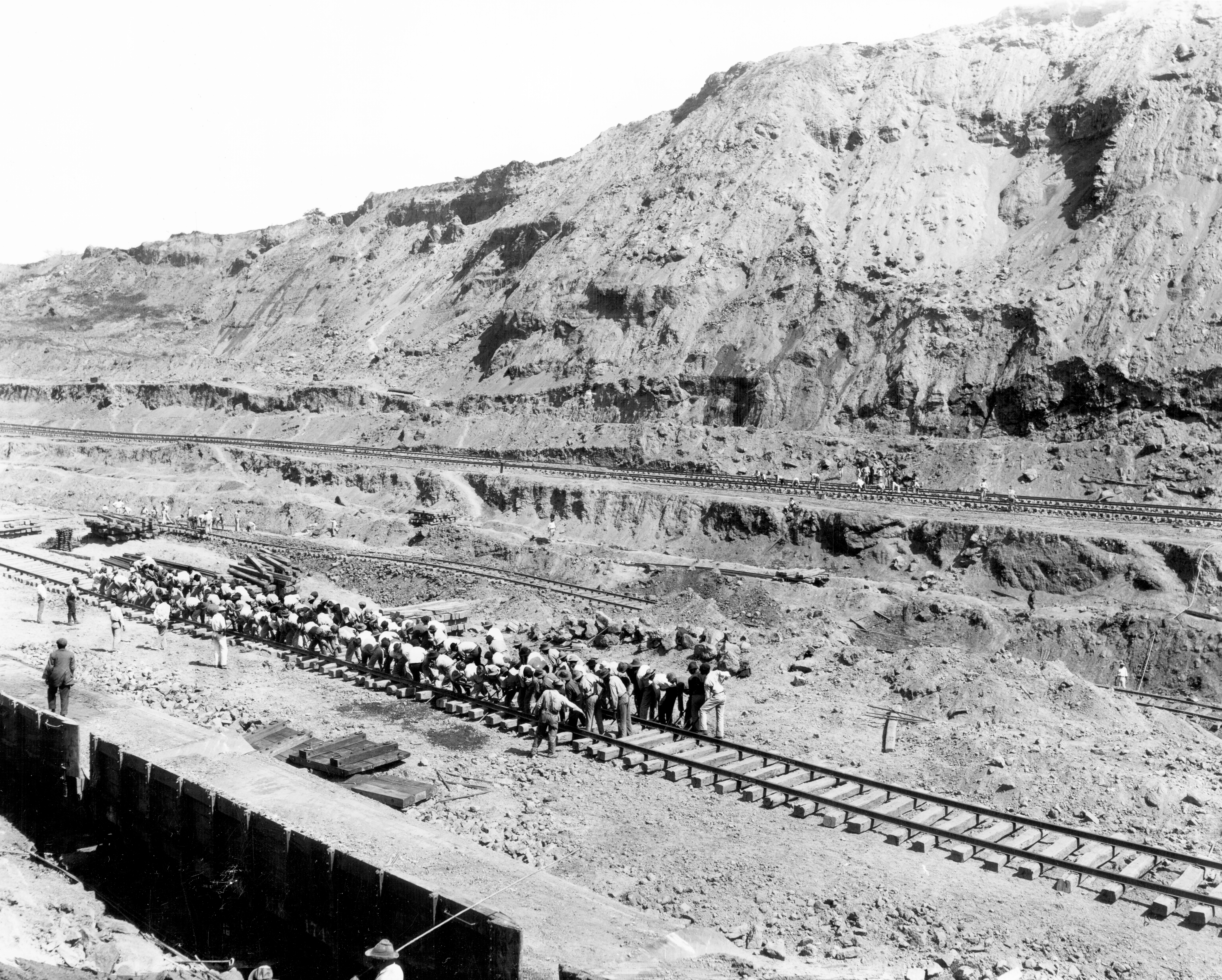
To create the Canal, a tremendous amount of material had to be removed. Relocating dirt efficiently was the most significant challenge of early construction. The railroad was essential to the operation, creating a conveyor belt to move the mountains of earth. By the end, the U.S. excavated over 240 million cubic yards of material or more than 17 million dump trucks.
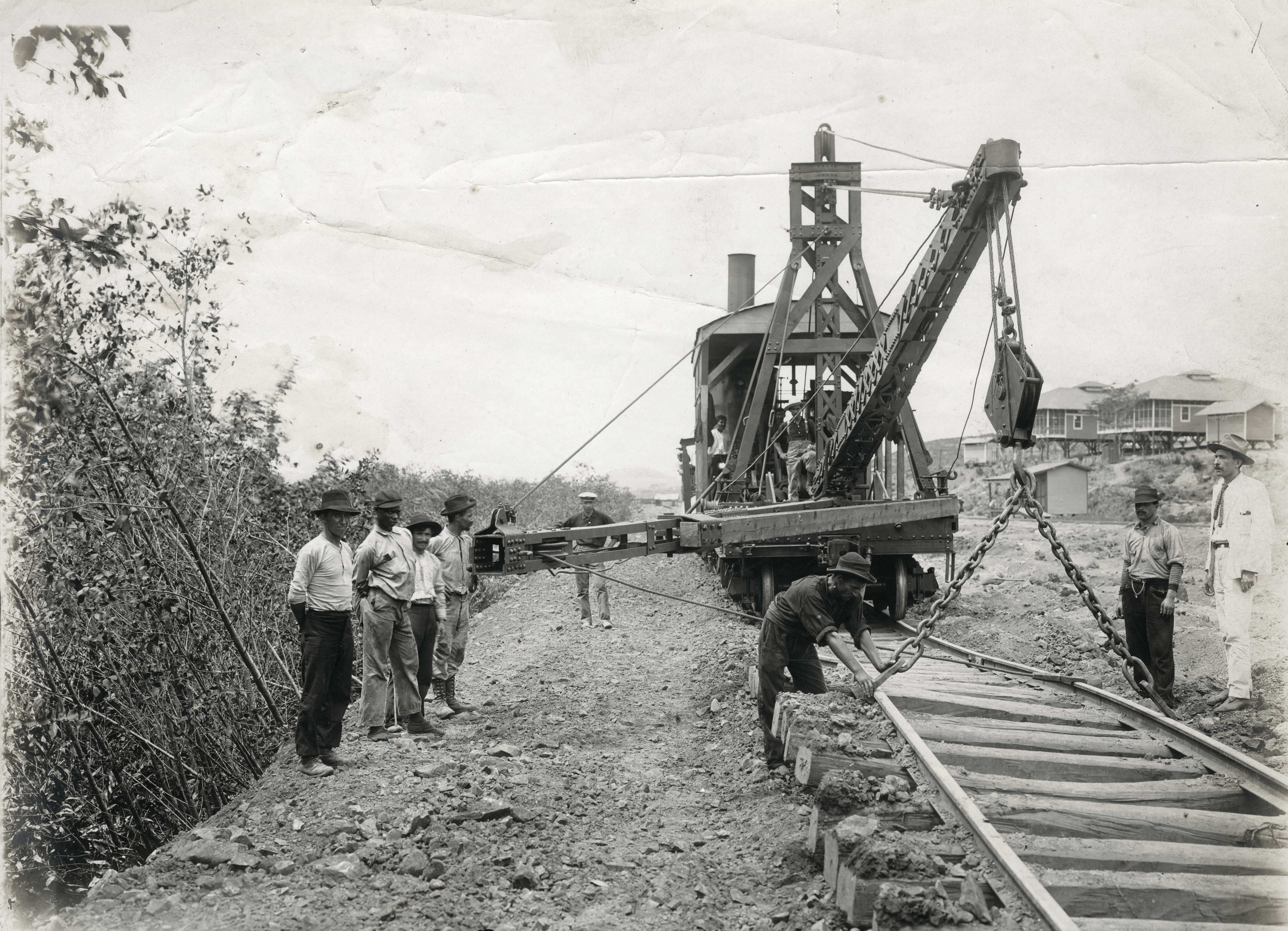
Equipment was continuously improved and adjusted to address issues in real-time. The Isthmian Canal Commission (ICC) encouraged manufacturers to come to Panama to see the work for themselves. Onsite workers also invented new tools to improve the process. One of the most significant inventions was the track shifter. Created by the Panama Canal Railroad manager, the specialized equipment significantly sped up the process of moving railroad track. The first version could move track up to 3 feet. Eventually, with redesigns, a team of 12 could use the shifter to replace the work of 600 men and move the track an impressive 9 feet in either direction.
Lidgerwood Unloader, 1914. II.2022.93.11. Gift of Mickey Fitzgerald.
Dirt Train, n.d. II.2021.36.106. Gift of Brad Wilde.
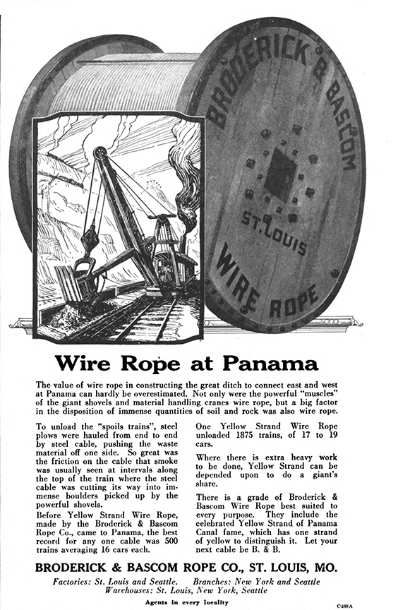
Broderick & Bascom Advertisement from Scientific American, November 1920.
The Lidgerwood Unloaders increased the efficiency of moving material by rapidly emptying the dirt trains. When the wire rope that pulled the critical plow failed to withstand the wear, Broderick & Bascom Co. employees went to Panama. They spent 24 days in the Canal Zone studying the problem and returned to St. Louis to design a wire rope that could hold up against the strain and friction. They reinforced their already famous “Yellow Strand” by adding another layer to create the 1 ½ inch thick “Brobas” wire rope.
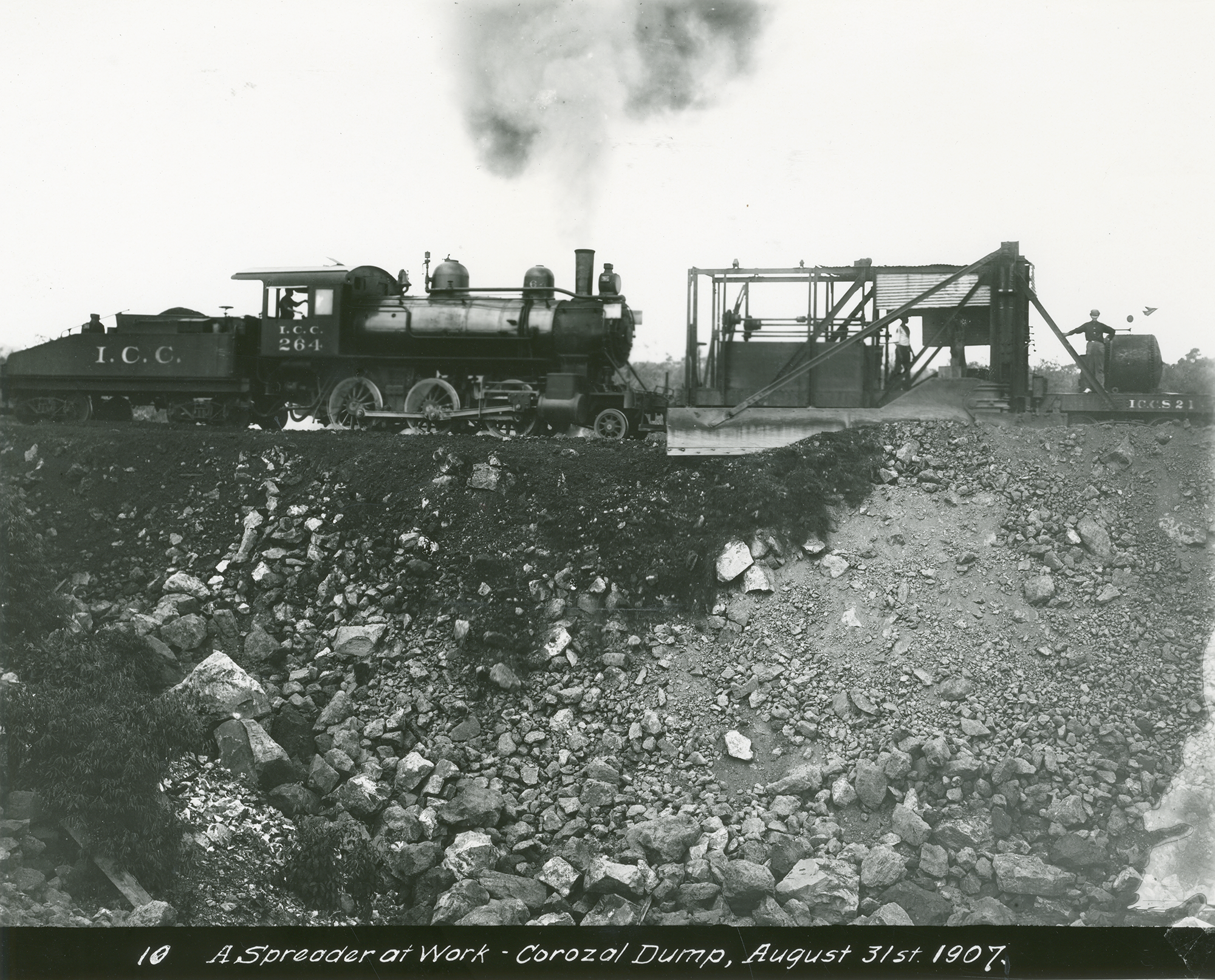
Dirt Spreader, 1907. 2011.25.19.
After unloading the dirt, a dirt spreader used an 11 ½ foot-long steel blade to distribute material. It did the job of several hundred men working with shovels. Around 50 improvements were made to the spreader during the 10 years of construction.
Men shifting track with track shifter, n.d. 2001.74.1.3. Gift of Doris and Ken Tuley.
Men shifting track by hand, n.d. II.2019.999.554.
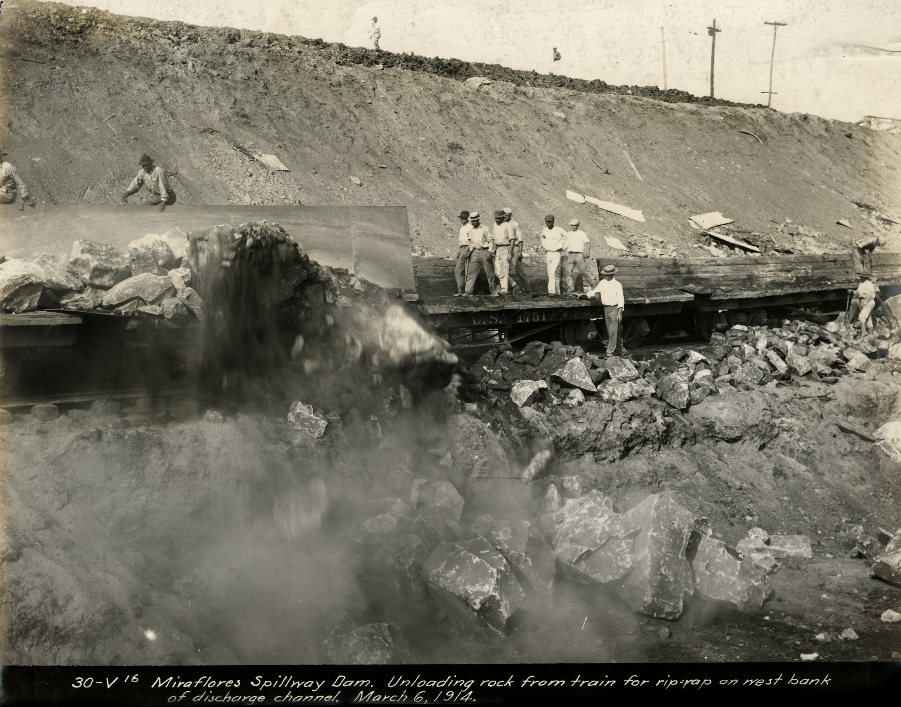
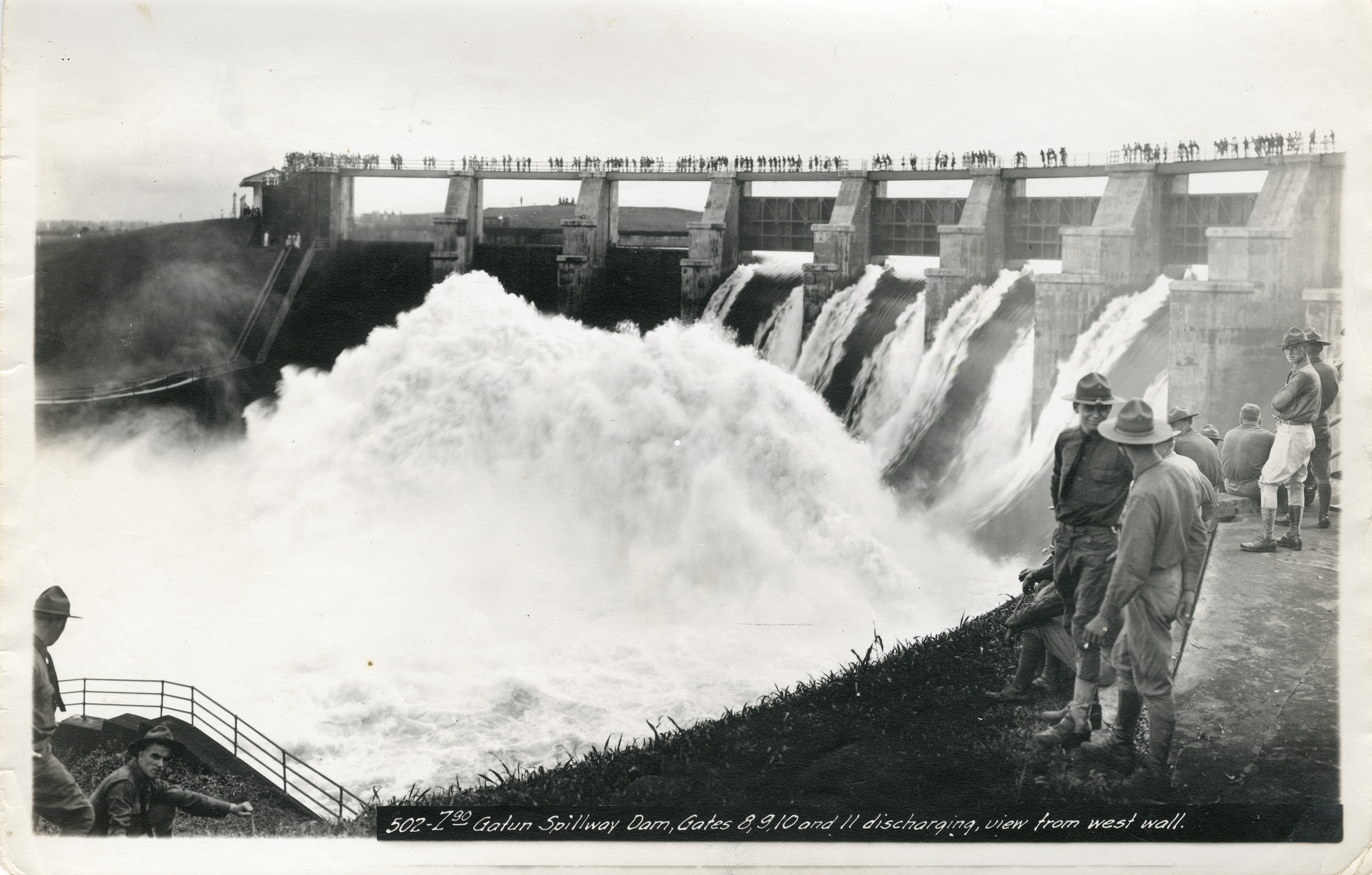
U.S. engineers determined that managing the Chagres River through a dam and spillway at Gatun was the key to success. They used it to fuel the hydroelectric plant that powered the Canal and to provide the 52 million gallons of water necessary to move a ship from one ocean to the other.
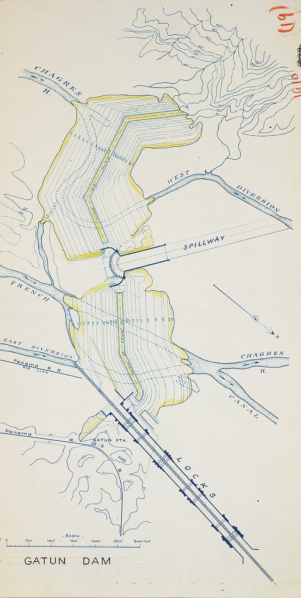
At the time of its construction, Gatun Dam was the largest earthen dam in the world. It measures 0.5 miles thick at the base, 1.5 miles long at its crest, and 105 feet above sea level at its highest point. A concrete spillway at its center releases excess water. The dam eventually created Gatun Lake.
The choice to build an earthen dam was another controversial and debated decision. Some engineers believed a masonry dam was needed. However, extensive boring samples and soil composition testing suggested that the location lacked the solid foundation that a masonry dam required.
Plan of Gatun Dam from A.B Nichols Notebook Folio R, n.d. Image Courtesy of The Linda Hall Library of Science, Engineering and Technology.
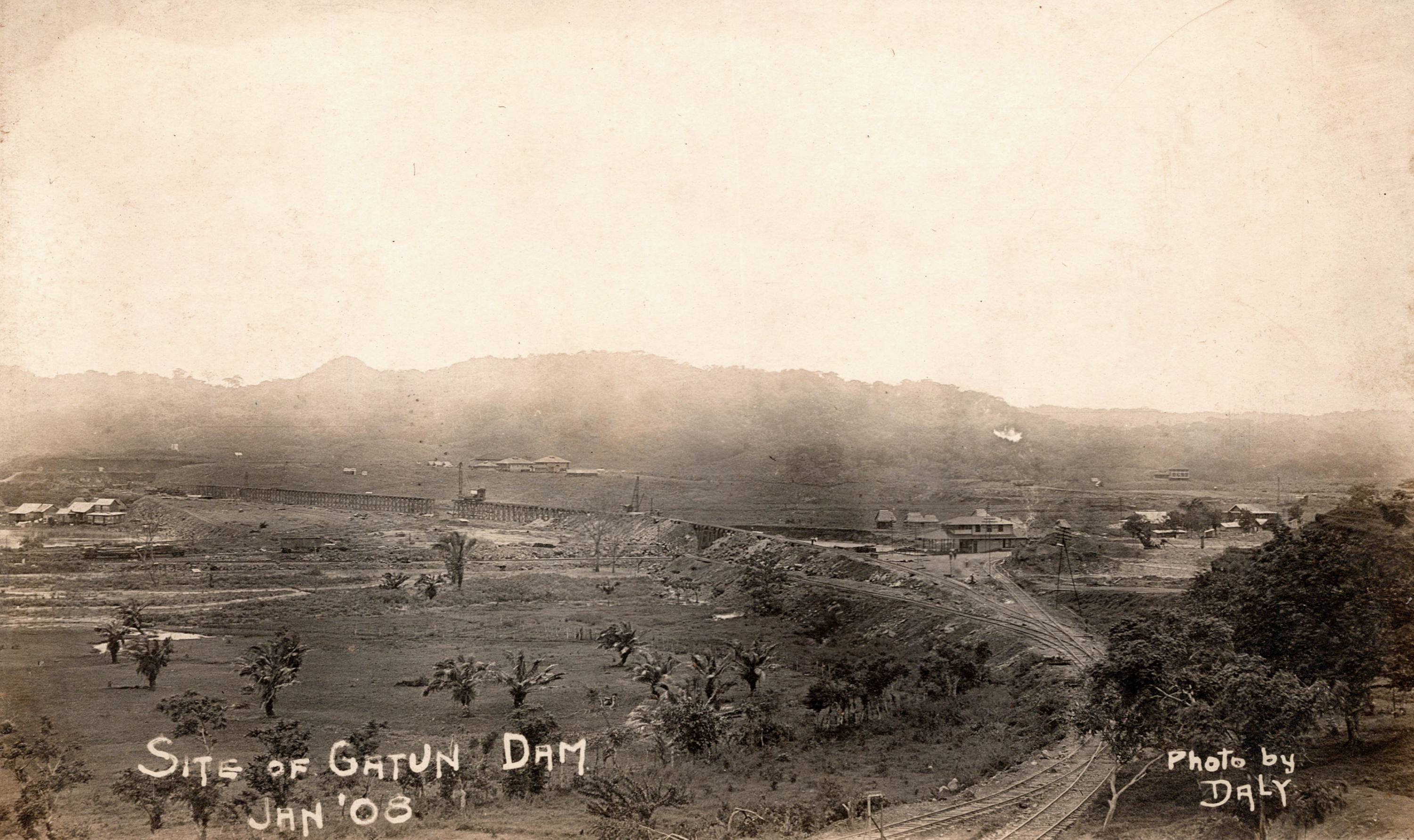
Daly, Gatun Dam Site, 1908. II.2021.36.106. Gift of Brad Wilde.
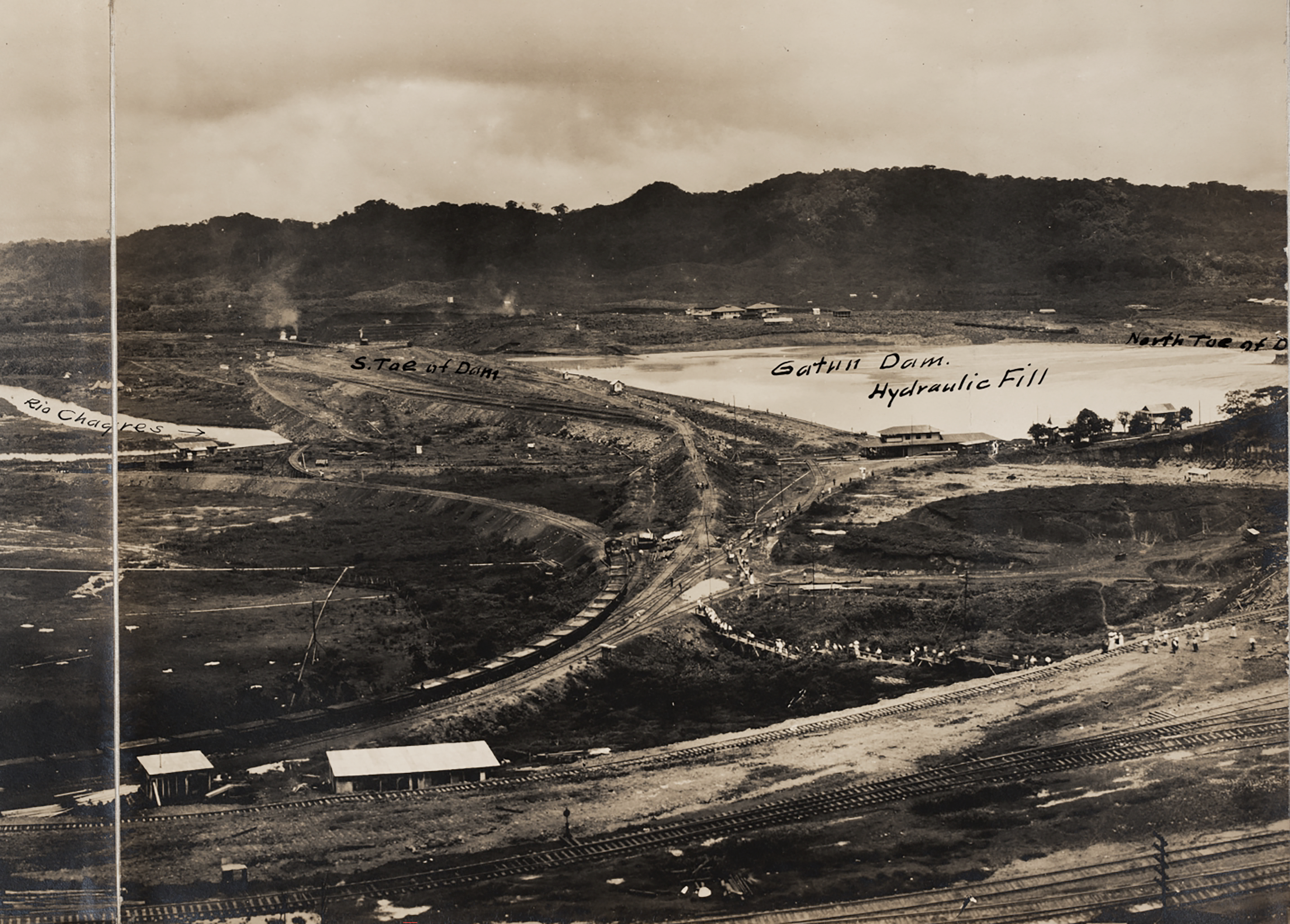
Construction of Gatun Dam, Hydraulic Fill from A.B. Nichols Notebook v.48, n.d. Image Courtesy of The Linda Hall Library of Science, Engineering and Technology.
To build the dam, two wooden elevated railroad trestles were built across the Chagres River valley with 1000 feet between them. Rock from Culebra Cut was dumped off the trestles to create two ridges or toes. Next, a hydraulic filling process was used to pump dredged mud in between them. The water eventually drained and left behind a packed core. Dry fill was piled on top until it reached the necessary height. Over 23 million cubic yards of rock were used in the dam’s construction.
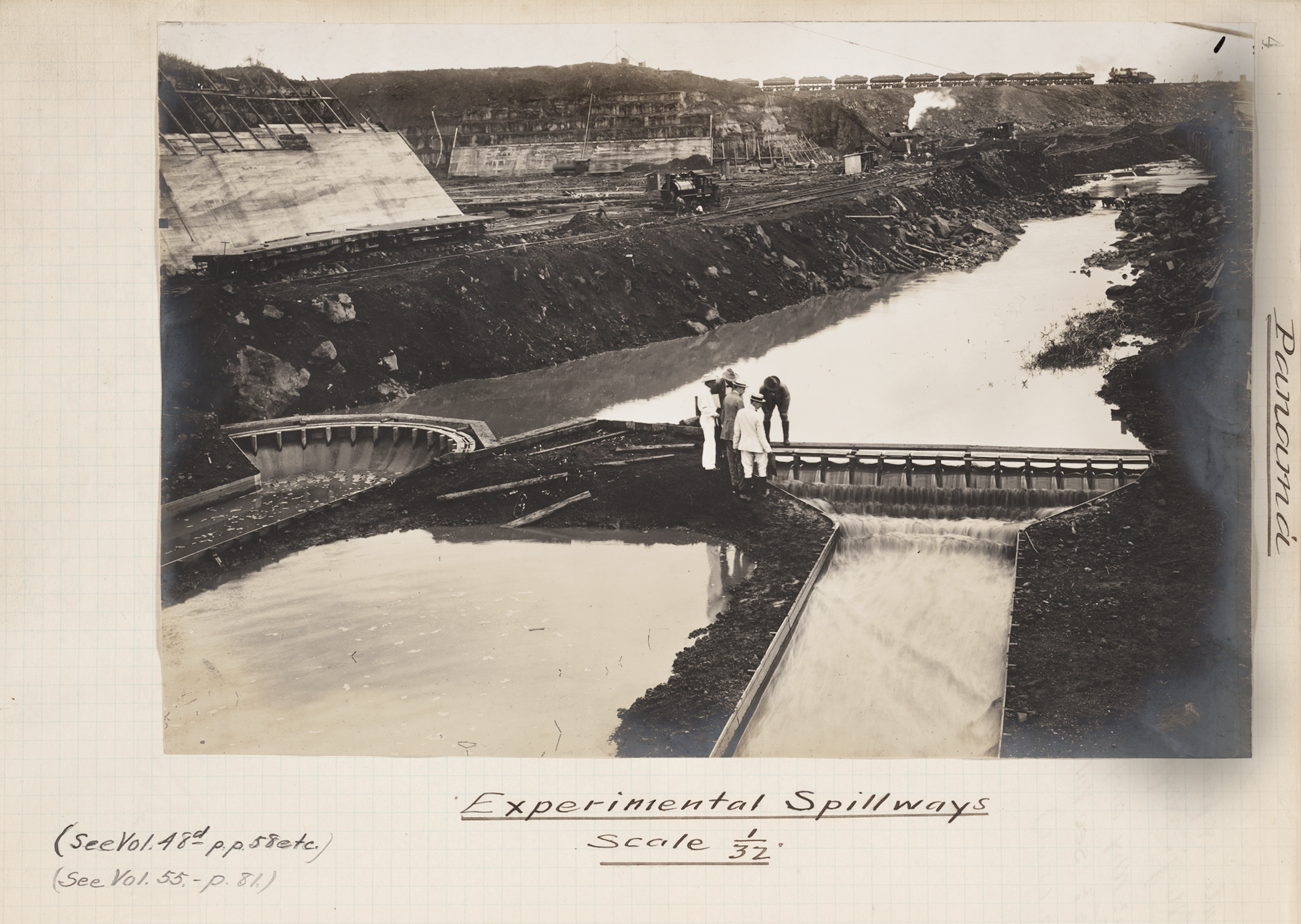
Experimental Dams at Gatun from A.B. Nichols Notebook v.41, n.d. Image Courtesy of The Linda Hall Library of Science, Engineering and Technology.
Gatun Spillway, n.d. 2008.18.2.19. Gift of Emily Murphy.
Submerging 164 square miles, Gatun Lake was the largest artificial lake in the world at the time of its creation. By 1906, it was determined that the lake’s surface needed to be 85 feet above sea level. Data on rainfall, floods, water level, and flow from old records and numerous hydrological and meteorological stations throughout the region guided the calculations. Despite the many unknown variables, construction of the Canal progressed. A historic flood in 1909 caused them to reconsider, and a new maximum height of 87 feet was established.
Despite conducting topographical studies as late as 1912, engineers still had only an approximate understanding of the lake’s ultimate shoreline. Questions also remained about whether the water would hold once it reached its intended height or if it would slowly seep through the ground.
Taking measurements near Tabernilla, n.d. II.2020.32.1. Gift of the Estate of Mr. and Mrs. Thorndike Saville, Jr.
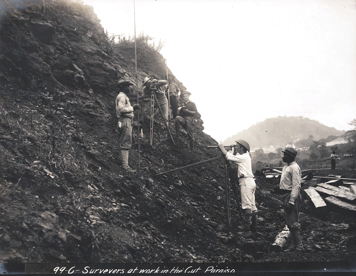
Surveyors in the Cut from A.B. Nichols Photograph Album 2, n.d. Image Courtesy of The Linda Hall Library of Science, Engineering and Technology.
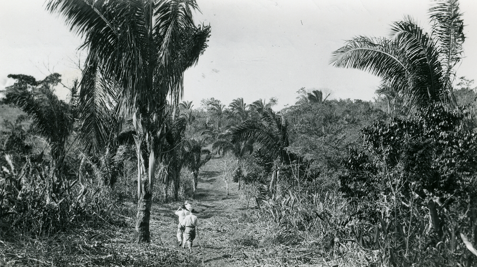
Homer Cornthwaite, Trail from Culebra to Arrijan, n.d. II.2022.8.7. Gift of David B. McMahon.
Homer Cornthwaite was a photographer and worked as a meteorologist during the construction of the Canal. Many of the weather stations they monitored were in distant and hard-to-reach places.
Closing of the Chagres River at Gatun from A.B. Nichols Photograph Album 2, August 1907. Image Courtesy of The Linda Hall Library of Science, Engineering and Technology.
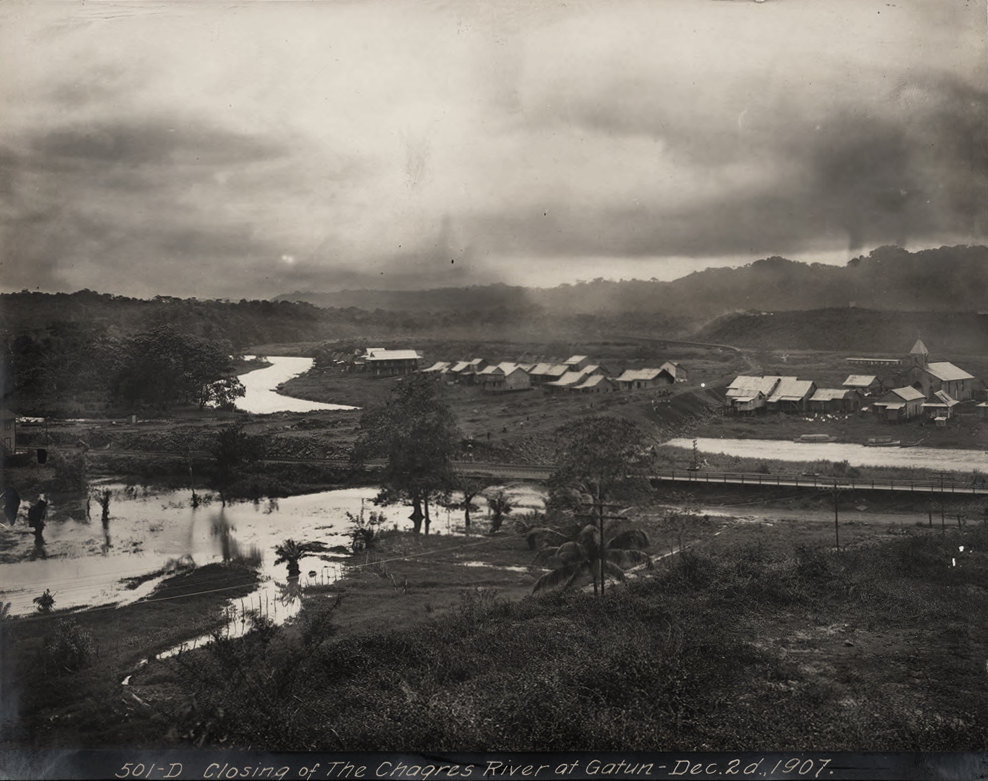
The Gatun Dam, Locks, and Lake are named after the town once located underneath the dam. The construction of the Canal destroyed “Old Gatun” and many other communities. The rising water of Gatun Lake also displaced many residents. In these photos from 1907, you can see the early stages of blocking the Chagres River and the devastation of the town.
Closing of the Chagres River at Gatun from A.B. Nichols Photograph Album 2, December 1907. Image Courtesy of The Linda Hall Library of Science, Engineering and Technology.
Gatun Lake, Dying Jungle, 1914. II.2022.93.16. Gift of Mickey Fitzgerald.
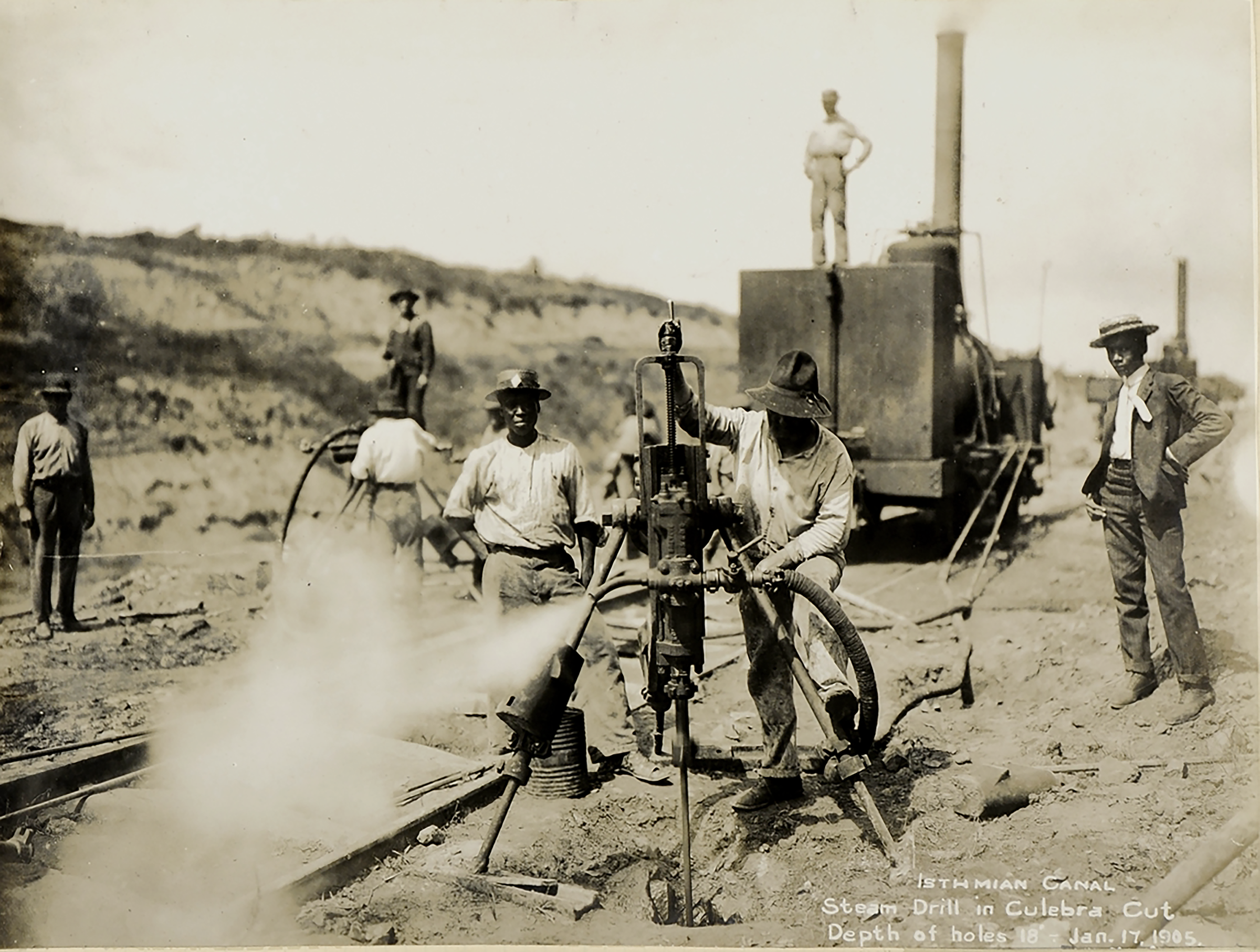
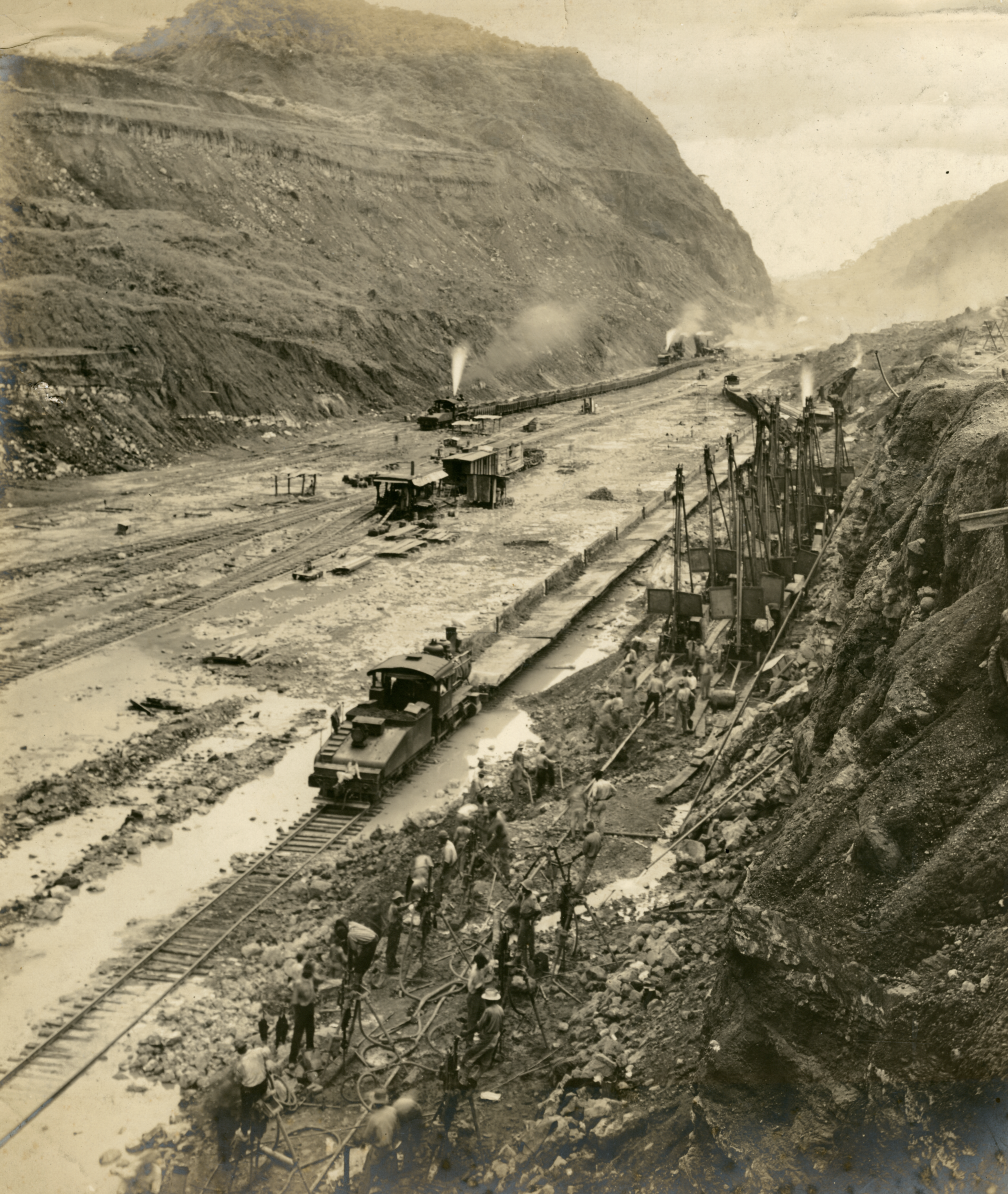
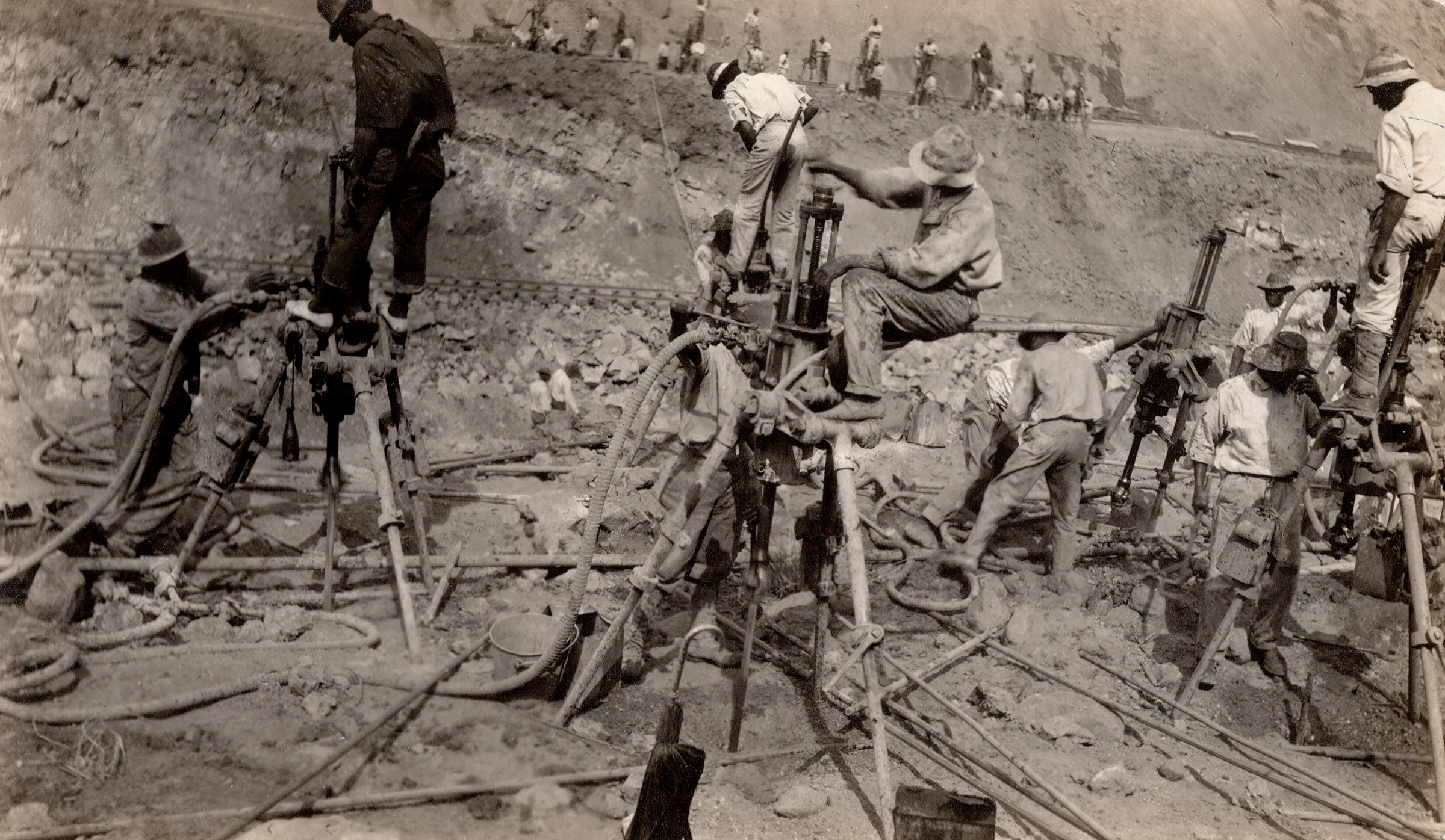
Building Gatun Dam was one of the two most significant challenges of the Canal. Across Gatun Lake lay the other—the Culebra Cut. It required the deepest excavation of the Canal. Using over 300 drills, dynamite, steam shovels, trains, and dredges, as many as 6,000 workers a day cut through the continental divide. At the peak of construction, a train moved in or out every minute of the workday. In the 7 years it took to complete, the Cut was never quiet. The noise only dulled during the night as construction progress shifted to maintenance, repair, and refueling equipment.
The sound of a modern music concert is an average 100 decibels, similar to one piece of modern heavy construction equipment. Imagine working in an area with hundreds of pieces of equipment, thousands of men, and walls hundreds of feet tall to amplify the sound—all with no hearing protection.
Steam Drill in Culebra Cut from A.B. Nichols Notebook B-4, 1905. Image Courtesy of The Linda Hall Library of Science, Engineering and Technology.
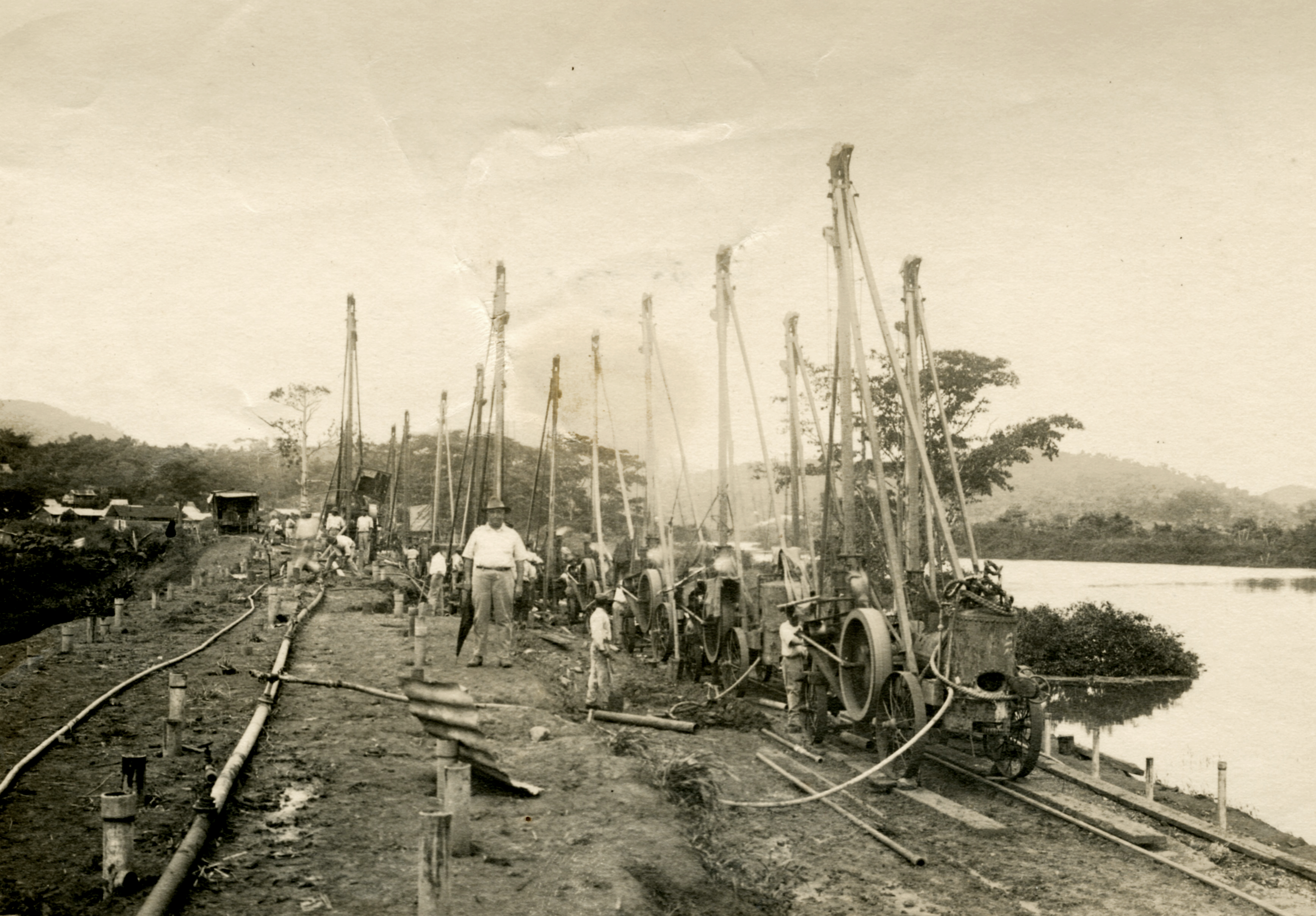
Well Drills in Culebra Cut, August 1913. II.2022.93.43. Gift of Mickey Fitzgerald.
Compressed Air Drill Attached to Air Pipe from Murray Family Photographs, n.d. II.2020.48.5. Gift of Rob Cintron.
Three air-compressing plants were built to operate the drills in Culebra Cut. The water supply for the steam shovels and compressed air for the drills were a considerable problem since the equipment was constantly being relocated. Nine miles of parallel pipe mains for water and air ran along each side of the Cut. At intervals of 500 feet, lateral mains ran over the edge and fed into the equipment nearby.
Drills in Culebra Cut, n.d. II.2021.36.106. Gift of Brad Wilde.
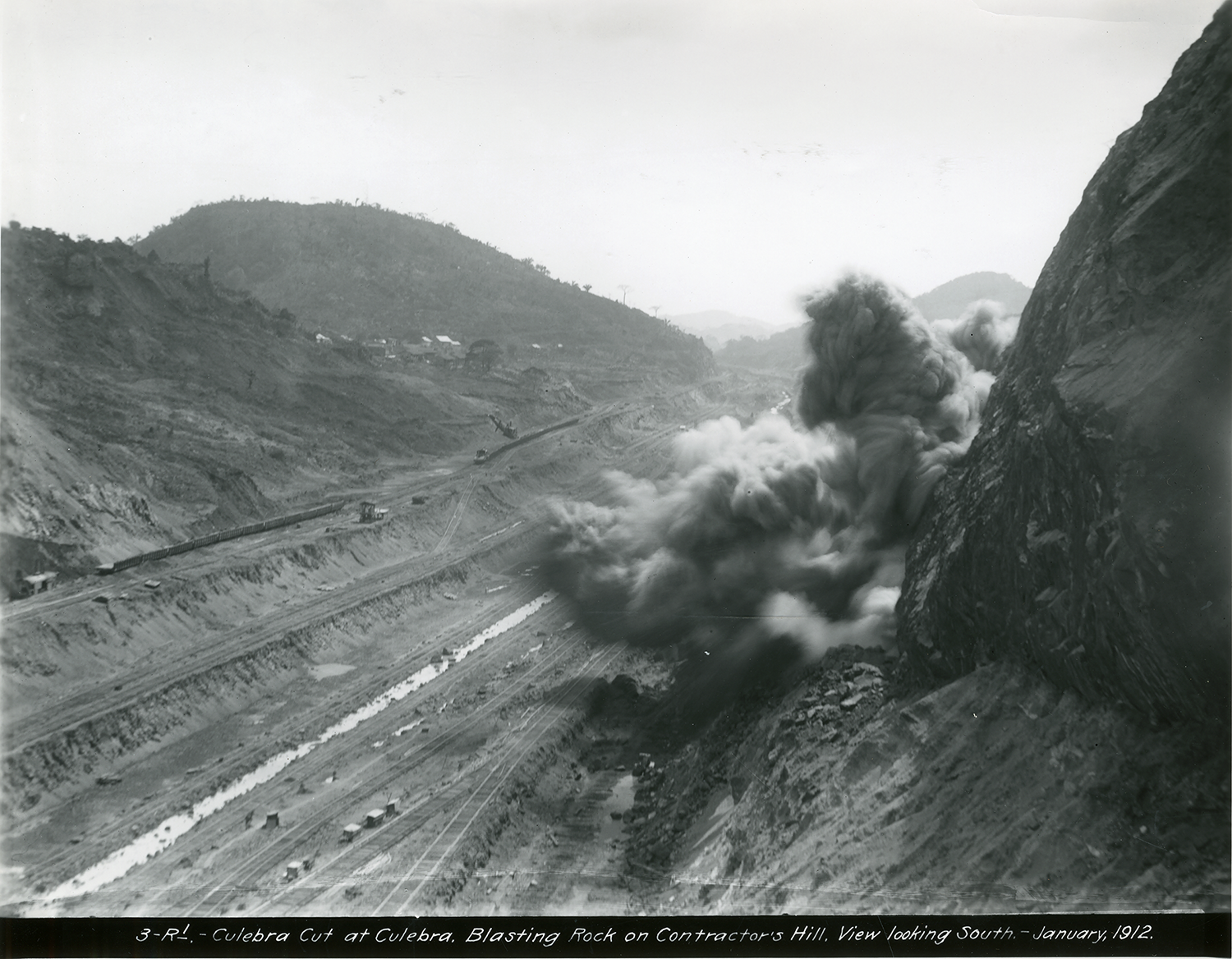
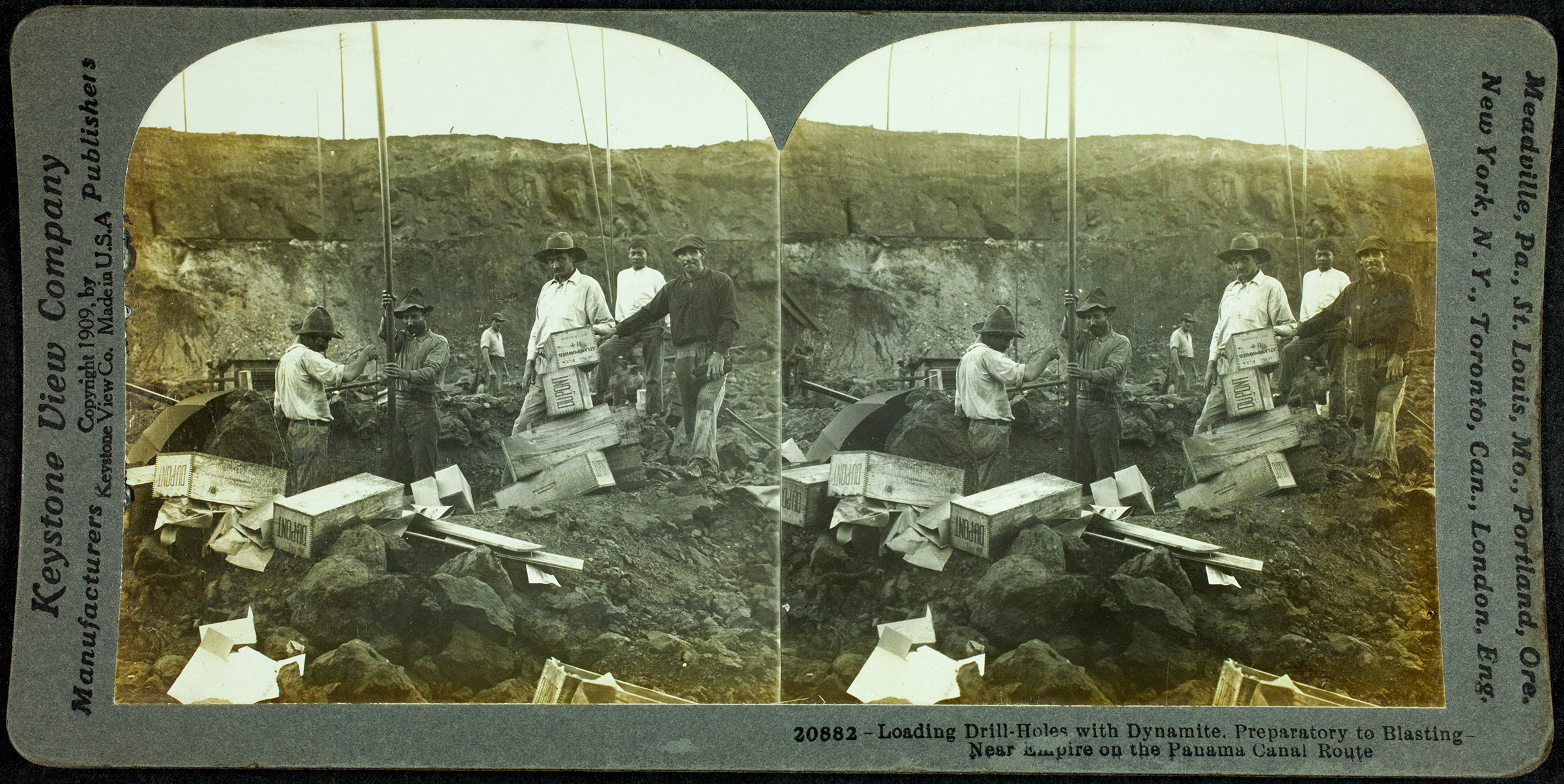
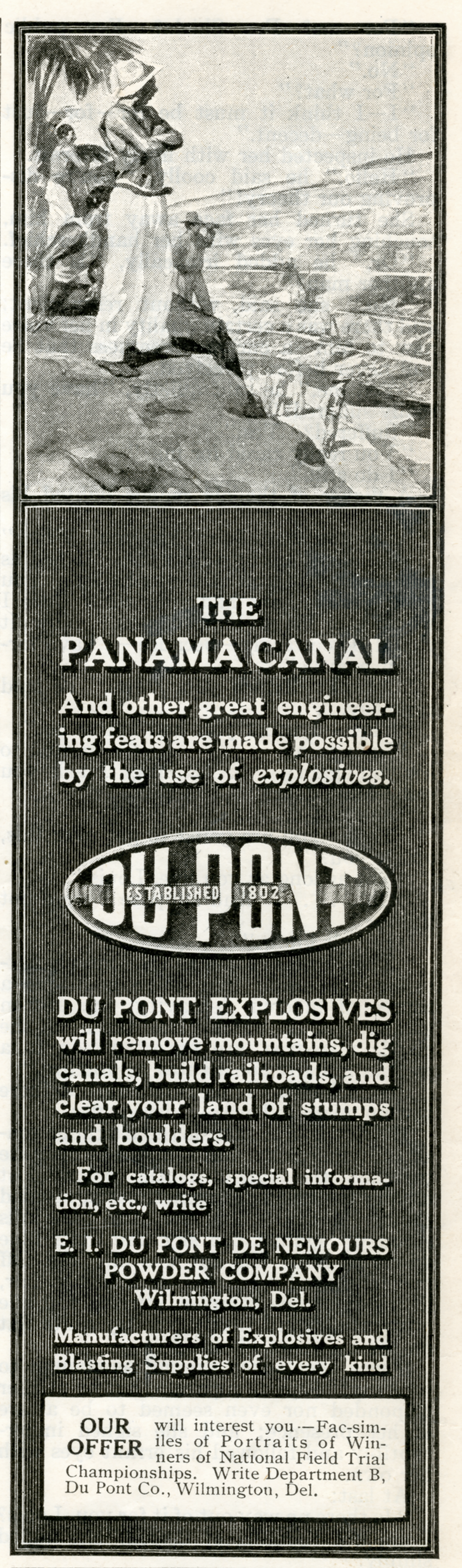
Canal engineers had the monumental task of breaking down soil and rock so that it could be removed. Dynamite was their answer. During construction, workers used over 60 million pounds of dynamite. Multiple U.S. manufacturers provided the enormous supply. The companies were proud of their contribution to the project and designed new products to meet the harsh working conditions. The largest supplier of dynamite for construction was DuPont. At the request of the Isthmian Canal Commission (ICC), they designed a more waterproof electric fuse that was better equipped to function in damp conditions. Instead of producing a special product and supplying it only to the Panama Canal, they upgraded their entire product line, benefiting all future users of their dynamite.
Explosion at Culebra Cut, 1912. 2003.100.43.32. Gift of Glenn W. Brandl.
Dynamite Shipment, n.d. II.2021.36.106. Gift of Brad Wilde.
Loading Drill Holes with Dynamite, 1909. Keystone View Company. 2013.2.167. Gift of William and Barbara Angrick.
Dupont Advertisement from Saturday Evening Post, 1908. II.2022.4.5.
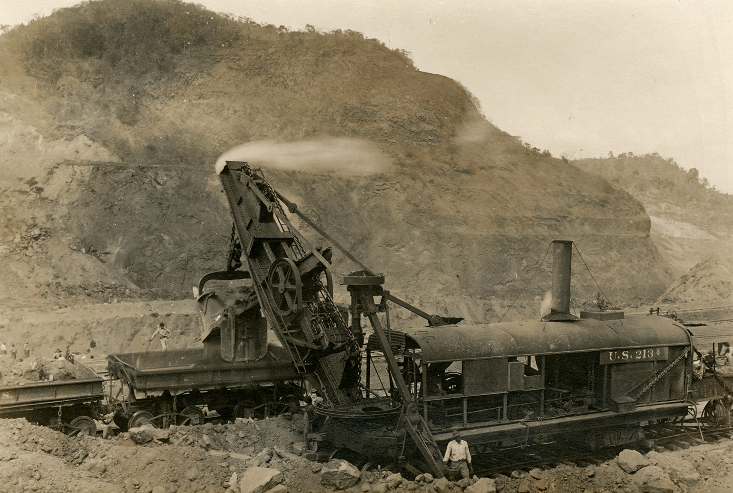
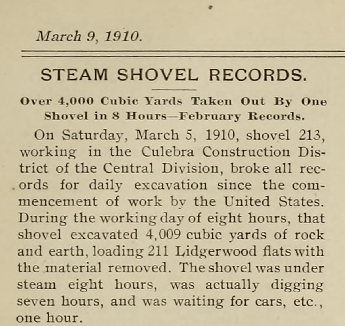
Steam shovels were the workhorses of the dig. In March 1909, 68 steam shovels were operating in Culebra Cut. The precision and movements of the shovels controlled the pace and efficiency of excavation. The company newsletter, the Canal Record, regularly reported how much each shovel excavated, creating competition between crews. On March 5, 1910, Bucyrus No. 213 set the record for a single shovel with 4,009 cubic yards of material. Not bad for a Saturday.
Shovel 213 from Murray Family Photographs, n.d. II.2020.48.5. Gift of Rob Cintron.
Canal Record, March 9, 1910.
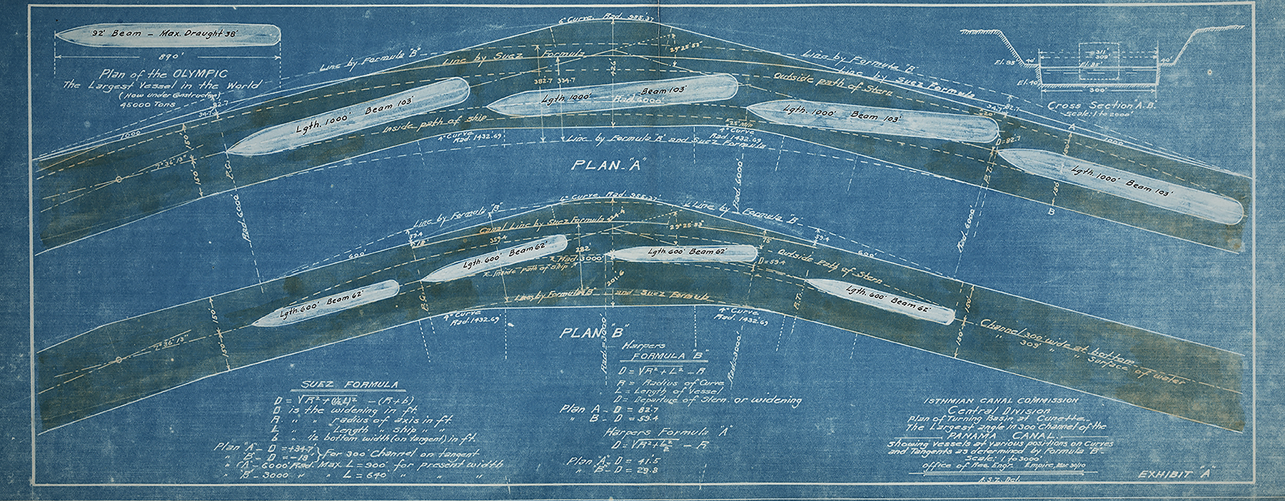
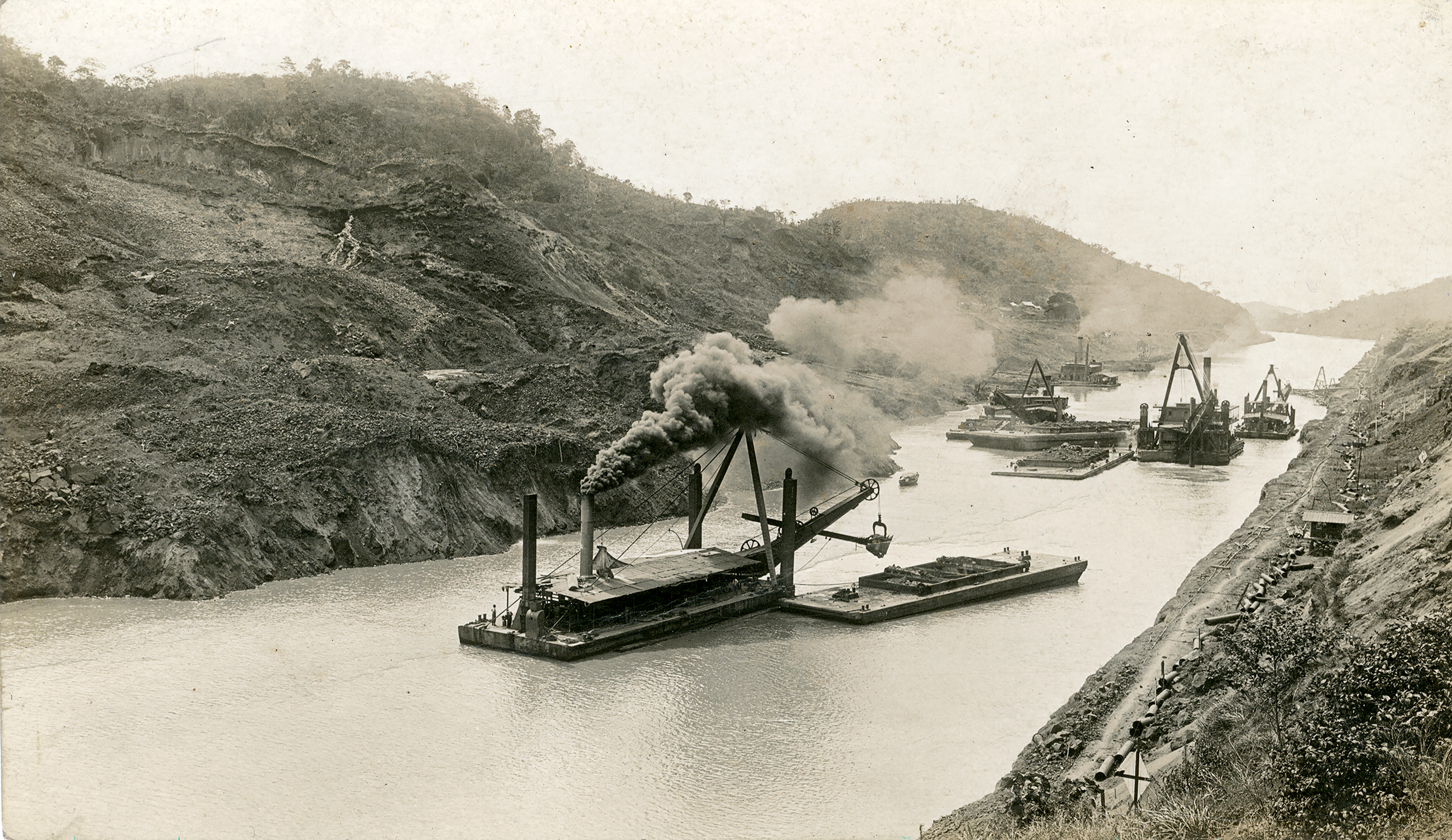
Dredges were responsible for almost half of the total material removed by the United States. They were used extensively in wet excavation and when possible helped increase the efficiency of dry excavation. Unlike steam shovels and dirt trains, dredges did not require track shifting or rebuilding. Many types of dredges were used, each designed and purchased for different materials and geologic structures—suction dredges were used on softer material, while dipper or ladder dredges were used on harder ground. Dredges were essential to keeping the channels of the Canal clear and wide enough to accommodate the turning angles of increasingly larger ships.
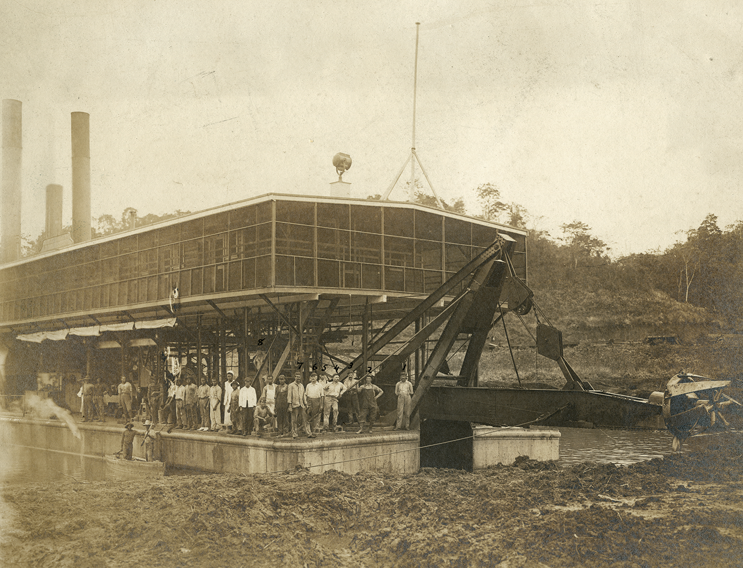
Sandpiper Dredge, 1910. 2013.5.1. Gift of Thomas Orr.
The Sandpiper was a suction dredge, equipped to run 24 hours a day. The machine’s crew of around 40 men lived on the second deck, screened to keep mosquitos away. While some dredges used steam as fuel, the Sandpiper used crude oil. The growing abundance of oil and gas allowed for engine advancements, and the power they could generate became an important component of the equipment used in construction.
Turning Basins from A.B. Nichols Notebook Folio M, n.d. Image Courtesy of The Linda Hall Library of Science, Engineering and Technology.
Dredges working in the Canal, n.d. II.2022.8.61. Gift of David B. McMahon.
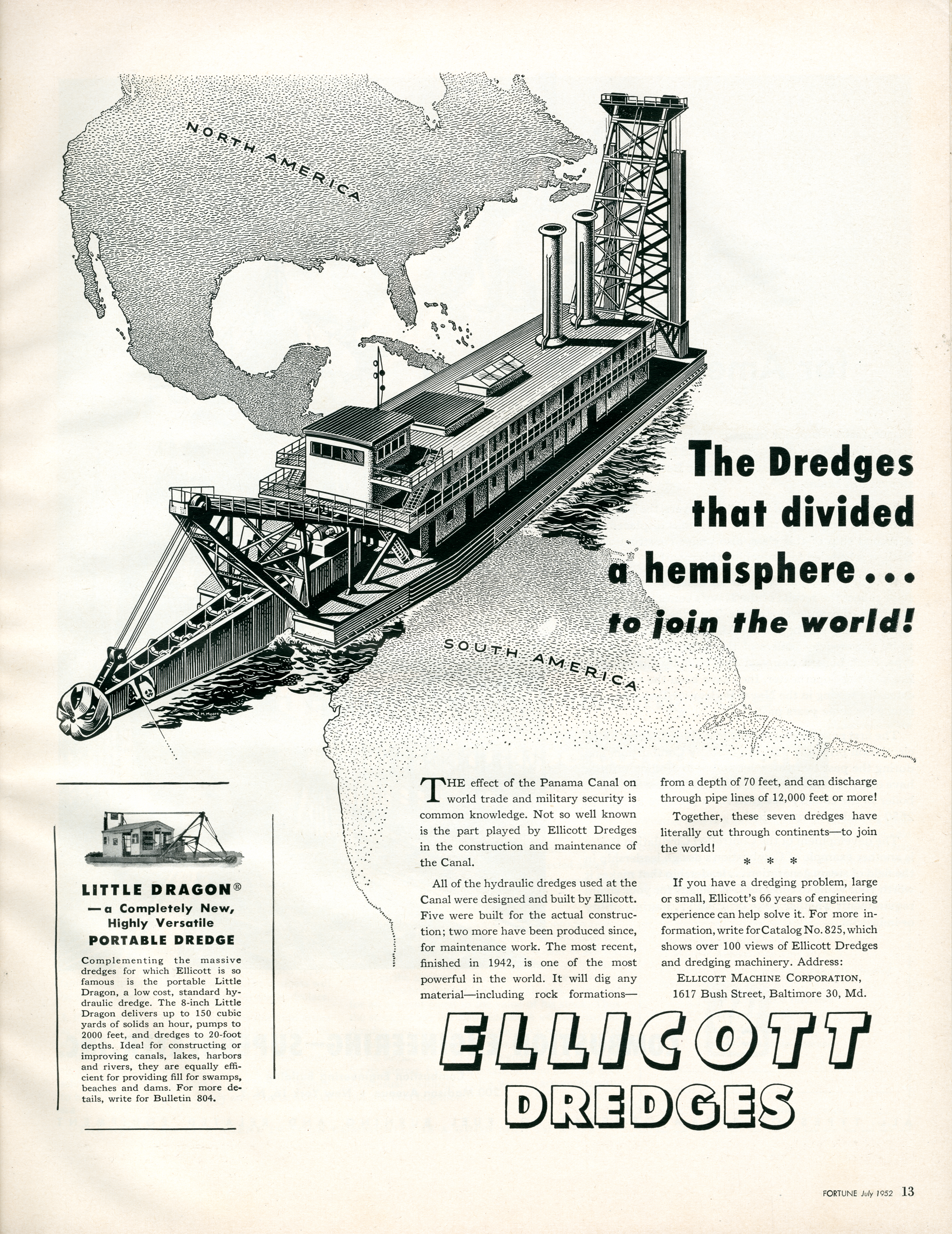
Ellicott Advertisement from Fortune Magazine, July 1952. II.2023.2.1.
Ellicott built cutter suction dredges used in the original construction. They also built the beloved Mindi dredge that was purchased for the Panama Canal in 1943.
Section of Area Flooded by Gatun Lake, Based on the maps General Plan of the Panama Canal From the Plans of the Panama Canal Company, 1900 and Map of the Canal Zone and Vicinity, 1927 2005.27.249, 2005.86.83 Map and Imagery Library
This map shows a selection of the general area submerged when the U.S. created Gatun Lake during the Panama Canal’s construction. A silhouette of Gatun Lake’s shoreline has been superimposed onto a map of the area before the existence of the lake and Canal. It allows you to understand the impact of the construction on the existing environment and on the people that lived and worked in the places consumed by the Canal’s path. You can see the names of established towns that were eventually flooded. Many smaller villages and homesteads are not represented. Some towns were relocated, their buildings dismantled and reassembled in new sites. Residents, however, had little say over the fate of the communities. The Panama Railroad, the first transcontinental railroad, was also relocated.
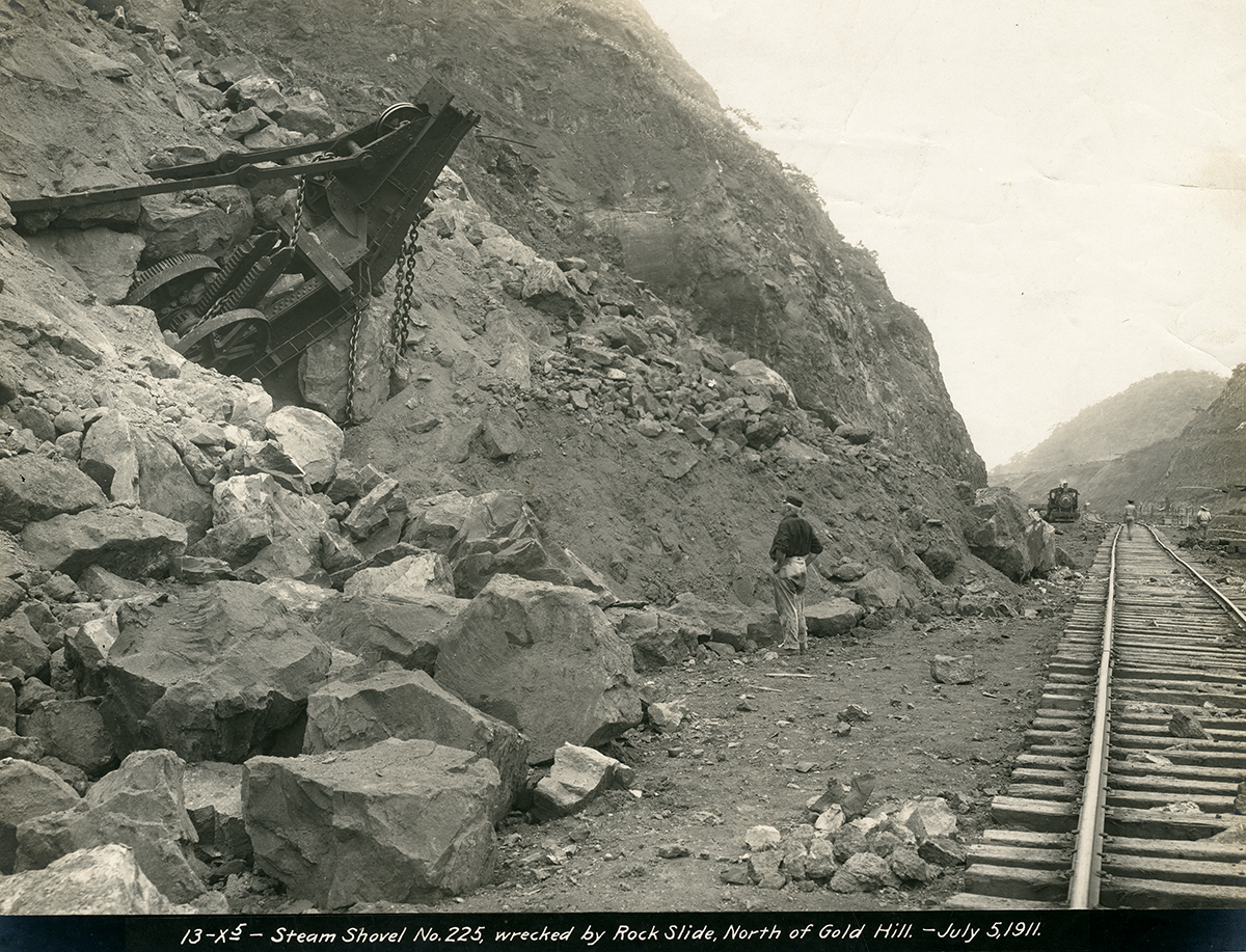
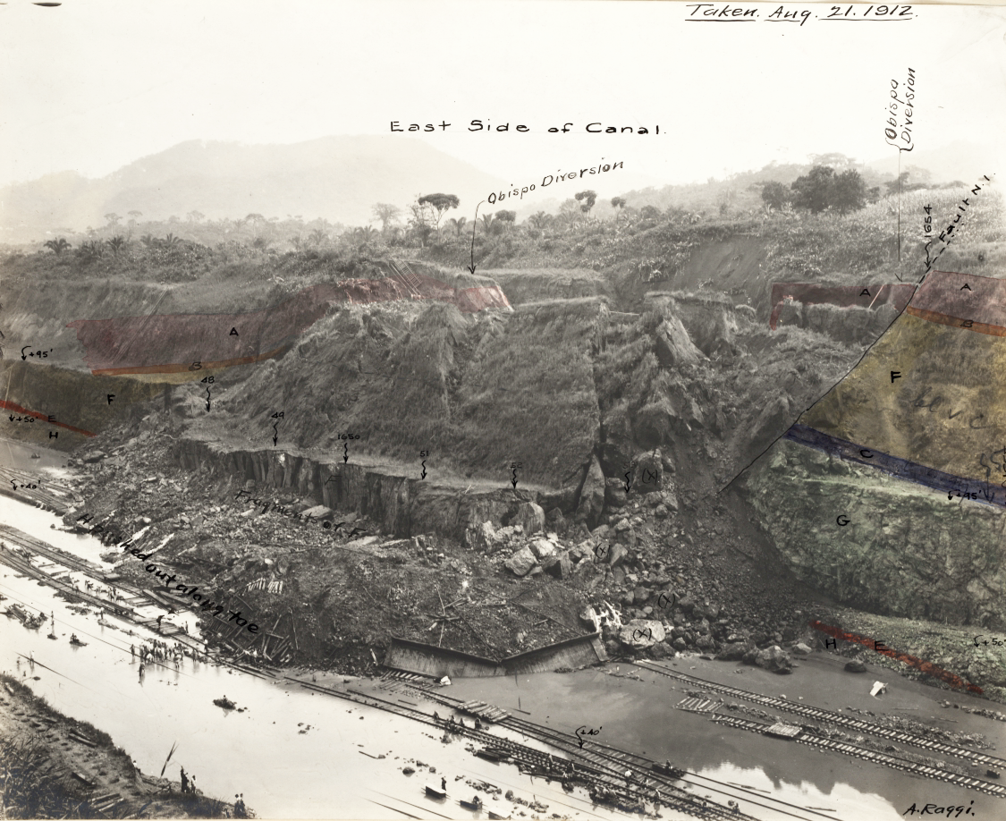
The landslides in Culebra Cut added 30 million cubic yards of material to the excavation. This was ¼ of the total amount of dirt removed. The landslides varied in type and length—some were material slipping, some were breaks, some lasted an hour, some lasted several days. It wasn’t until much later in the 1930s that the necessary mathematics for understanding landslides was developed.
Slide at Culebra, 1909. 2003.100.43.19. Gift of Glenn W. Brandl.
Several buildings in the town of Culebra, where many of the workers lived, were closed and moved because of the proximity of landslides. By January 1911, landslides had reached the clubhouse, the large building in the back right of the photo. Eventually, landslides took 75 acres of the town into Culebra Cut.
Tourists viewing Culebra Cut and slide at Cucaracha, 1914. II.2019.49.1. Gift of Mickey Fitzgerald and Carol Miller.
Tourists flocked to experience the monumental scale of Culebra Cut before the water was completely let in. Here dredges are finishing the excavation work in the background while material from a landslide is behind a group of sightseers.
Geological Map of Culebra Showing Probable Sliding Ground from A.B. Nichols Notebook v.T, n.d. Image Courtesy of The Linda Hall Library of Science, Engineering and Technology.
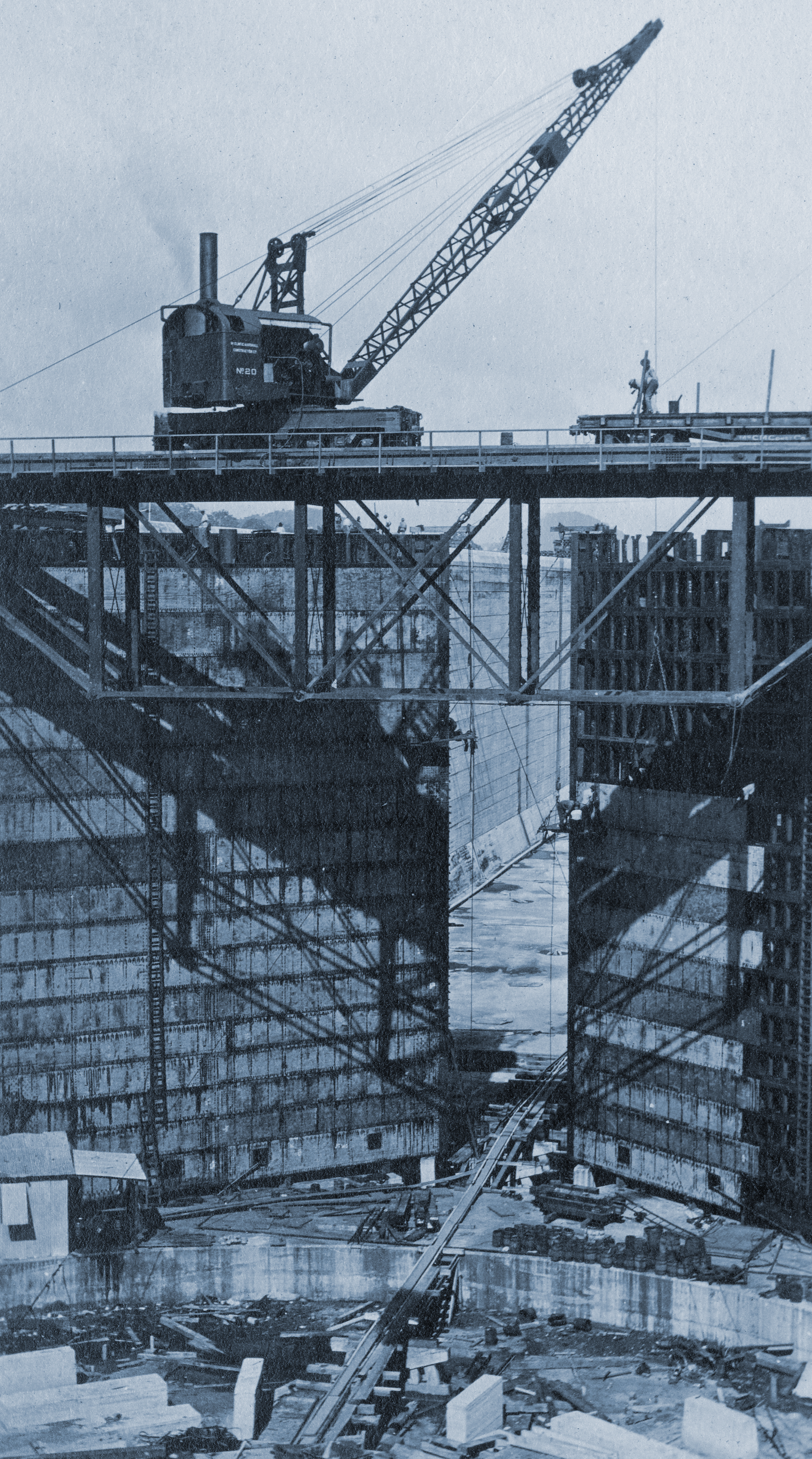
The three sets of concrete locks serve as two lanes of traffic with chambers that act as the “steps” to raise and lower the ships. Each chamber is 1000 feet long and 110 feet wide. The original dimensions increased during construction after the Titanic and its sister ships became the biggest ships in the world in 1911.
The locks were made using reinforced concrete, a relatively new construction method, only adopted by the U.S. Army Corps of Engineers in the 1890s. No concrete structure of comparable scale had ever been built, and the characteristics of the material when used in such high volume were unknown. Core samples were taken of the lock walls and floors during construction so the integrity of the concrete could be tested.
Cement use increased sevenfold in the years before the Panama Canal was built. Product availability and advancements in equipment played a role in the construction’s success.
Letter from Thomas Edison to the Chief Engineer of the Panama Canal, August 6, 1908. Library of Congress, Canal Zone Library and Museum Collection.
Letter from Thomas Edison to the Chief Engineer of the Panama Canal, August 6, 1908. Library of Congress, Canal Zone Library and Museum Collection.
Constructing Sidewall Monoliths, Gatun Locks, 1910. 2014.40.10. Gift of Dusty Graham and Ann Lafferty.
Workers constructed and placed forms, erected a skeleton of steel bars inside, and filled the space with wet concrete. After the concrete was dry, the forms moved to the next section.
Concrete Test Boring, Miraflores Locks, c.1913. II.2023.999.1.
Gatun Locks, 1913. II.2022.93.43. Gift of Mickey Fitzgerald.
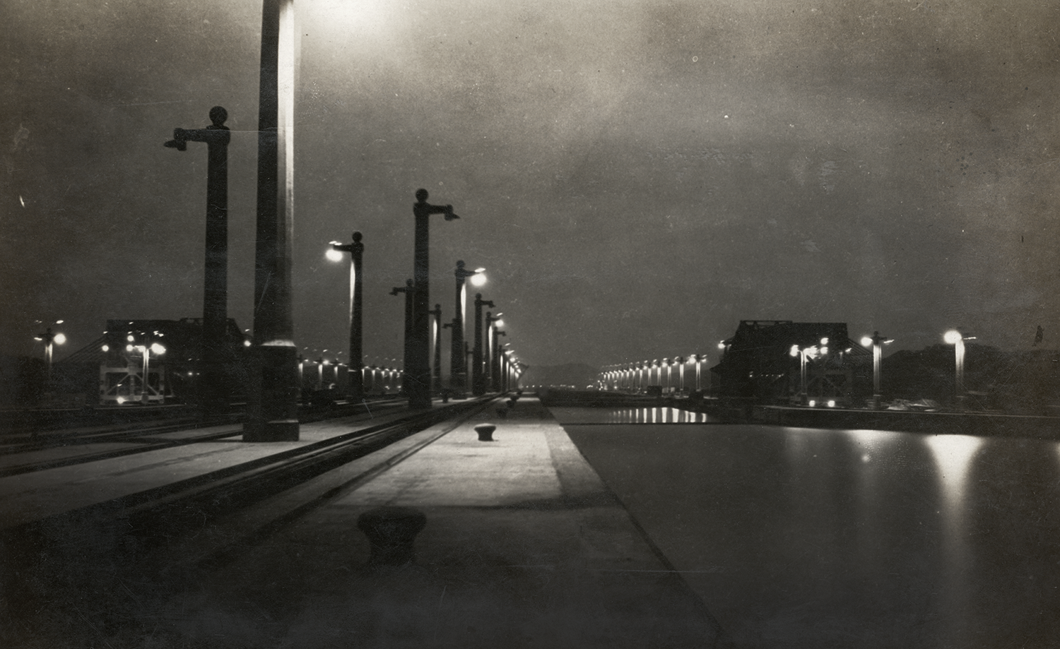
Electricity was the only form of power that made the function of the locks possible. Everything needed to be controlled from a single remote location with an instantaneous response time. At the time of Canal construction, electricity was not new, but the scale and complexity were extraordinary. The first building in Florida was electrified only a short time before, in 1883. It had 16 outlets.
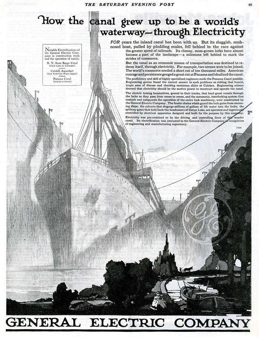
General Electric’s first major government contract was the Panama Canal. Although a small company at the time, they supplied the electrical equipment for the locks’ control boards and the towing locomotives. The design of the lock control boards was particularly critical. They function as a working, miniature model of the locks. The system forces the attendant to go through the precise process in proper sequence and does not allow for errors.
Locks at Night, n.d. II.2022.8.5. Gift of David B. McMahon.
Saturday Evening Post, December 29, 1917. II.2022.4.6.
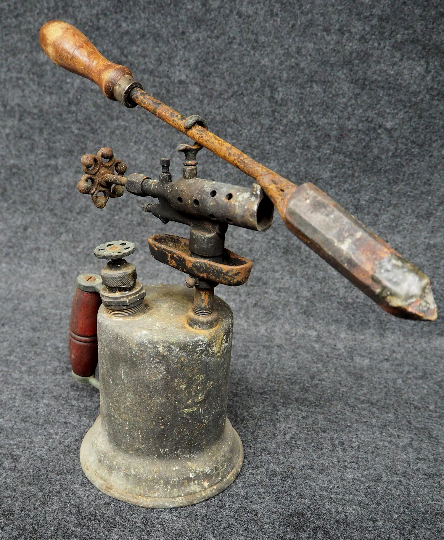
Brass Blow Torch and Soldering Iron, n.d. II.2019.91.1 & II.2019.91.3. Gift of Janice Scott.
This blowtorch and soldering iron belonged to Walter Hersh, a wireman for the Canal during construction. Tools of this type were used to connect wires during the installation of the electrical system.
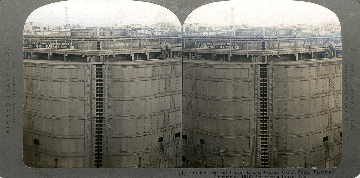
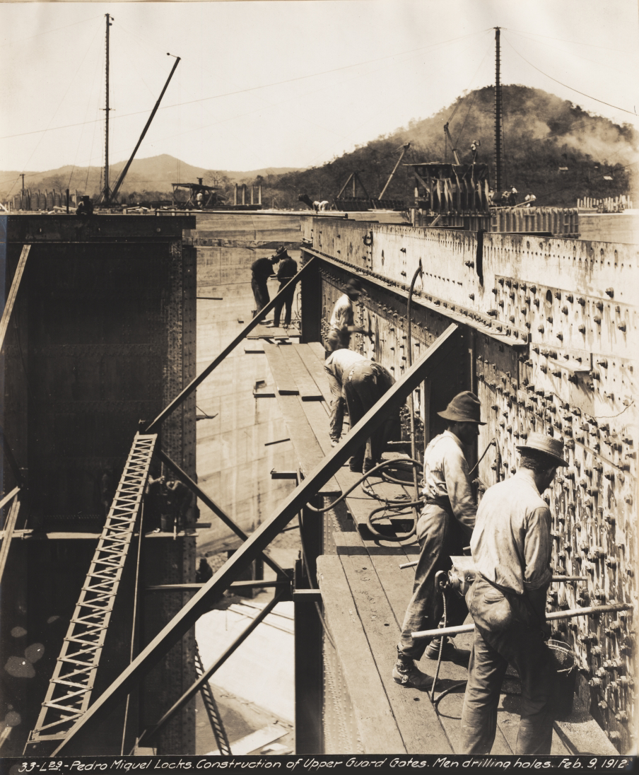
The gates used in the original Canal construction are miter gates comprised of two sides that meet at an angle or miter. They were the only element of the entire construction completed by a private company, McClintic-Marshall. Each side or “leaf” of the Canal gates is 65 feet wide by 7 feet thick and varies from 47 to 82 feet high. Even the shortest gate was taller than any other miter gate in the world. Although some leaves weigh over 745 tons, their design and the buoyancy of water makes them weightless when moving in the locks.
The U.S. purchased two identical floating cranes, Hercules and Ajax, capable of lifting the gate leaves. At the time, they were the largest floating cranes in the world. Hercules passed its initial load test. However, Ajax’s jib or operating arm collapsed during its test and had to be replaced. The cranes performed maintenance, salvage, and at least one rescue mission. They became iconic visuals of the Panama Canal.
Finished Gate at Gatun with McClintic-Marshall Sign, 1913. II.2019.999.554.
Lock Gates, n.d. II.2021.36.106. Gift of Brad Wilde.
Creating Holes in the Lock Gates from A.B. Nichols Notebook v.48a, n.d. Image Courtesy of The Linda Hall Library of Science, Engineering and Technology
Test of Floating Crane “Hercules”, 1915. 2001.23.60.4. Gift of Charles W. Hummer, Jr.
Failure of Test of Floating Crane “Ajax” from Murray Family Photographs, 1914. II.2020.48.5. Gift of Rob Cintron.
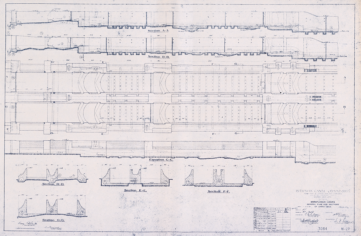
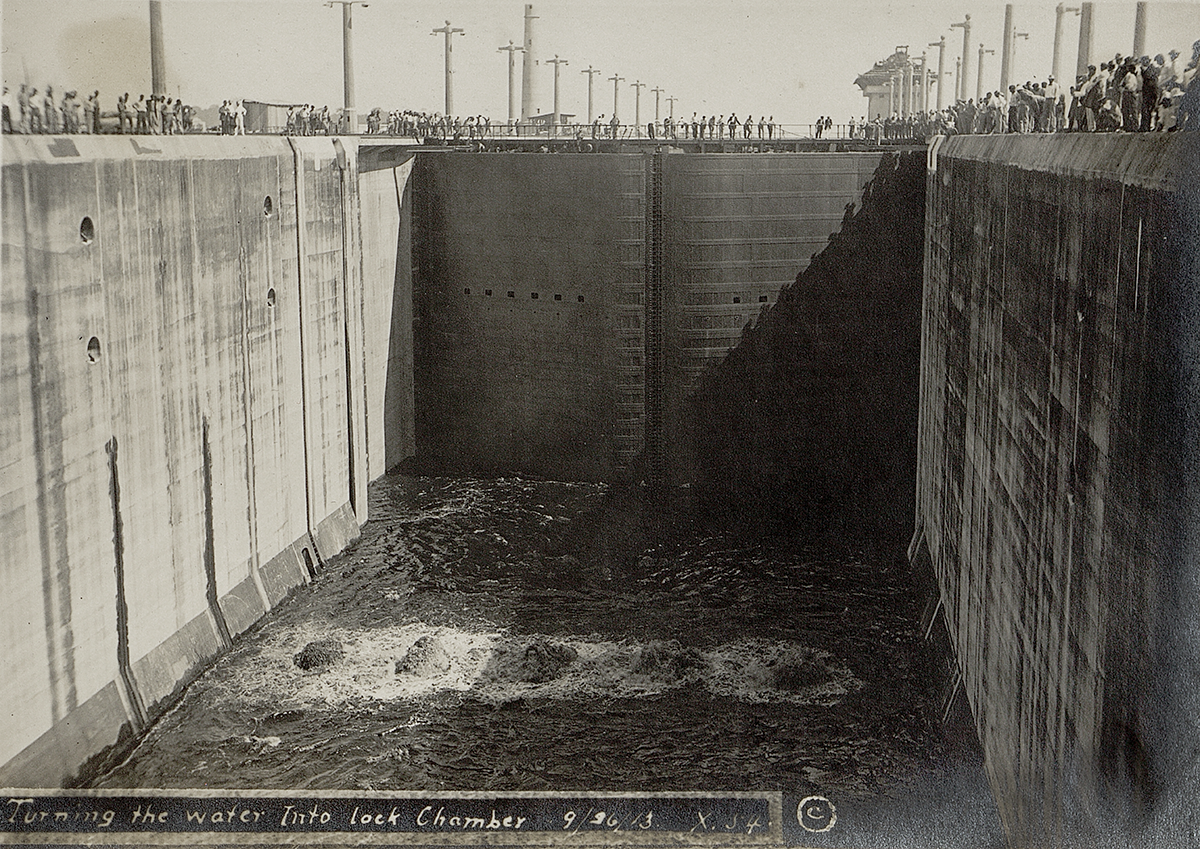
To fill the lock chamber, water flows into 18-foot diameter supply pipes in the center and side walls. From there, water enters the lateral tunnels that run underneath the floor, and spills into the lock chamber. The same pipes drain the chambers and lower the water level.
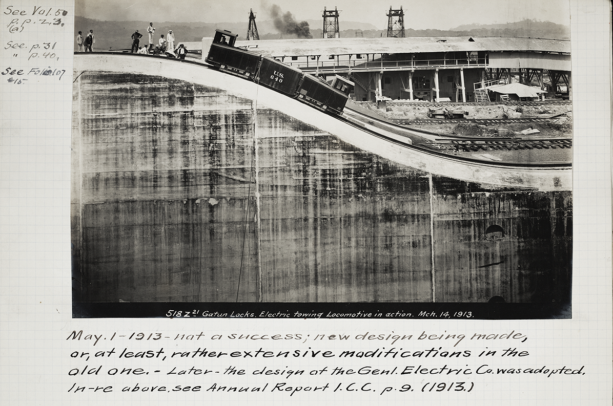
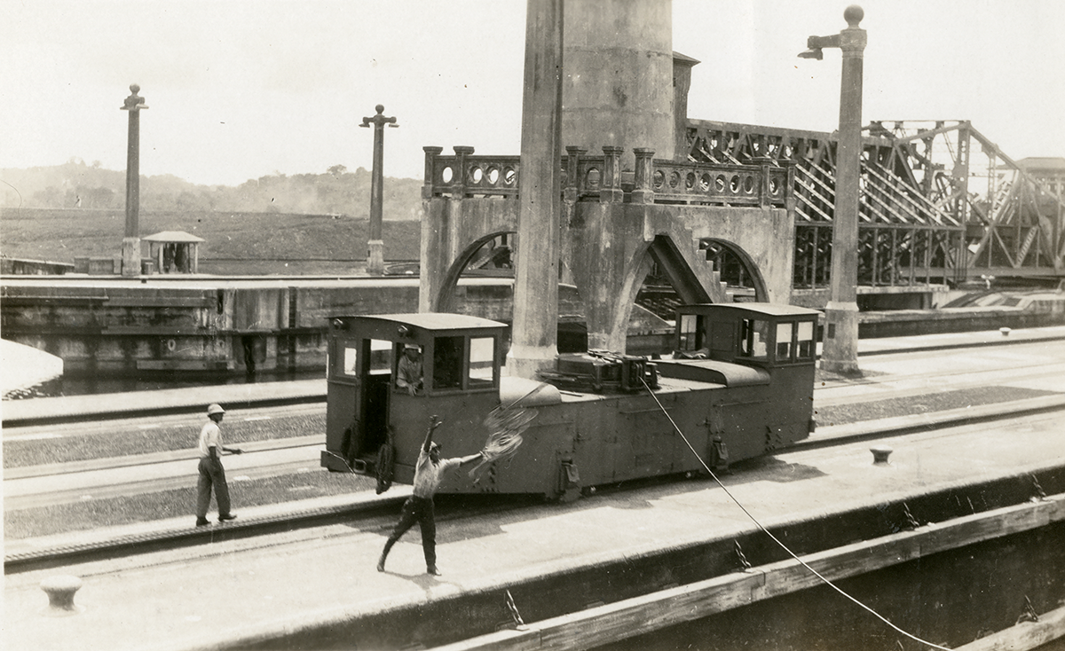
Electric towing locomotives or “mules’’ run along each side of the locks to control the ships. Animal mules had been used for centuries to move barges in canals, but in 1895, the idea of using electric equipment was experimentally tested. The Panama Canal’s locomotives were the first of their kind.The complex design and mechanical movements across the lock walls required precise calculations. Although their initial design failed preliminary tests, the final version became another iconic symbol of the Panama Canal.
Ships use up to eight locomotives to help move them through the locks and keep them centered in the lock chambers. The locomotives are attached to the ship with ropes expertly passed between line handlers on the lock walls and the ship’s deck. At the request of the Canal pilot, they can also act as brakes to slow a ship’s forward momentum.
Plan of Miraflores Locks, 1912. 2007.69.12. Gift of Loretta Date.
Water Entering the Locks from Album of Frederick Nobles, 1913. 2002.143. Gift of Helen Sheppard.
Ship Being Towed in Locks, n.d. II.2021.36.106. Gift of Brad Wilde.
Throwing Lines from Towing Locomotive, n.d. II.2023.2.2.
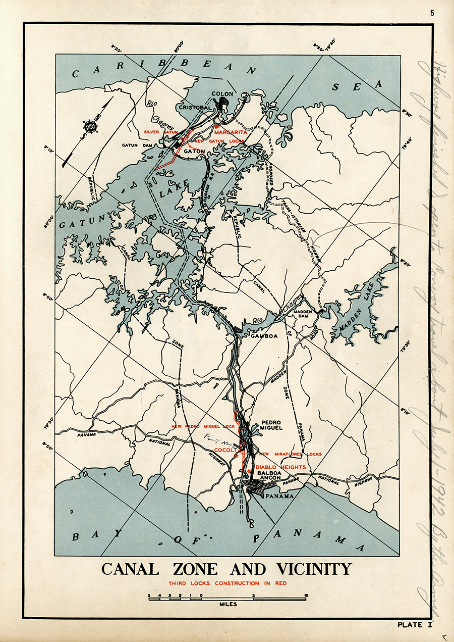
Throughout the 20th century, discussions about expanding or building a new canal continued. During the 1930s, a set of new locks was under construction, but the U.S. abandoned the project due to World War II.
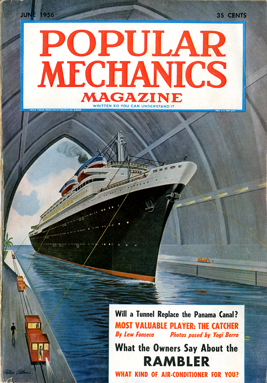
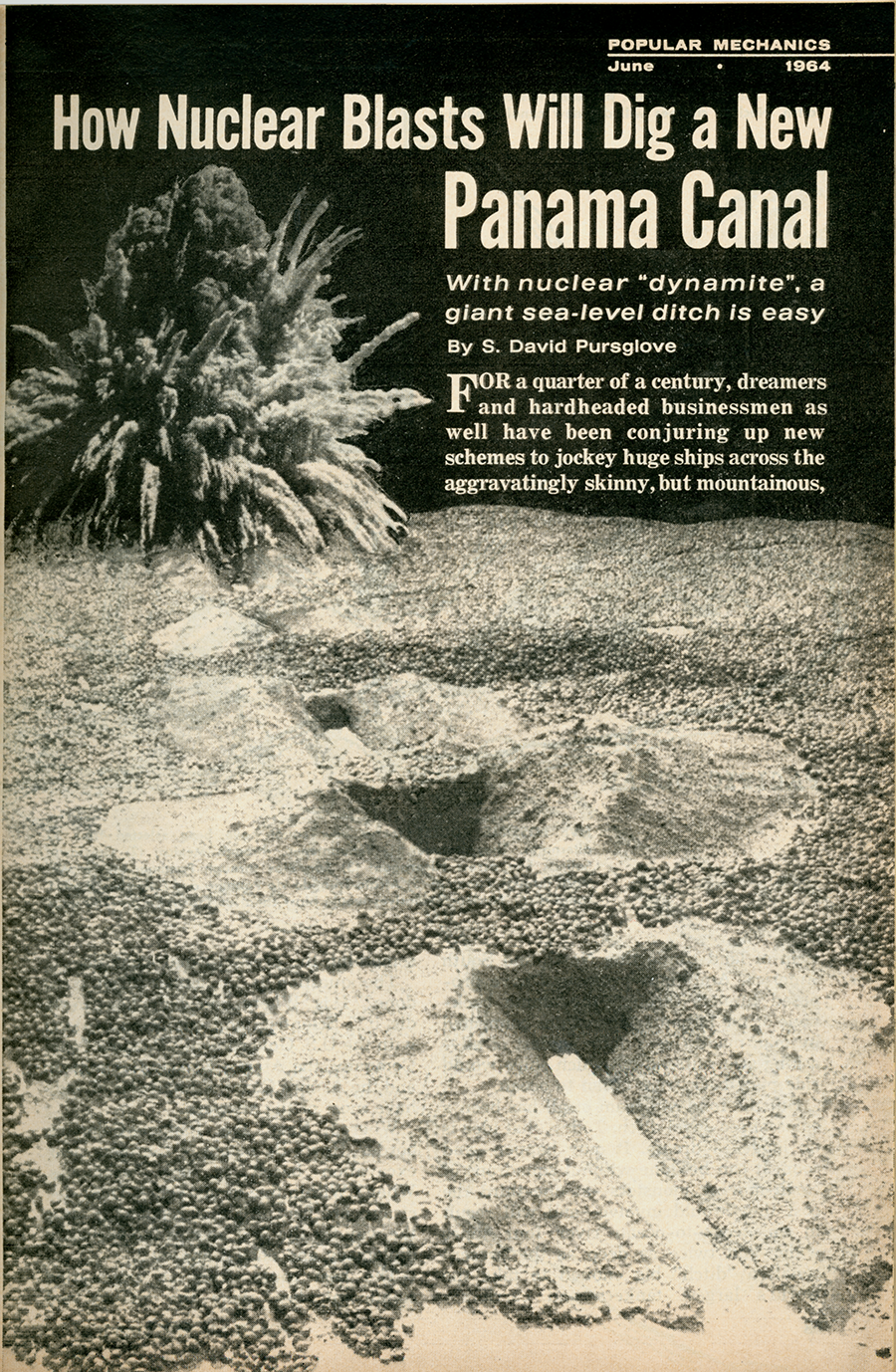
The concept of a sea-level canal persisted, and numerous studies were conducted on how best to do it. In the 1960s, the U.S. government released a study investigating the feasibility of using nuclear explosions to excavate a new sea-level canal in Panama. It is now known that a sea-level canal would have almost certainly been physically and financially impossible because of the soil composition—the same cause of the landslides that plagued the original construction.
Popular Mechanics, June 1956. II.2022.4.17.
Popular Mechanics, June 1964. II.2022.4.16.
Map of Third Locks Project from The Third Locks Project, 1941. II.2021.60.35. TC774.C428.
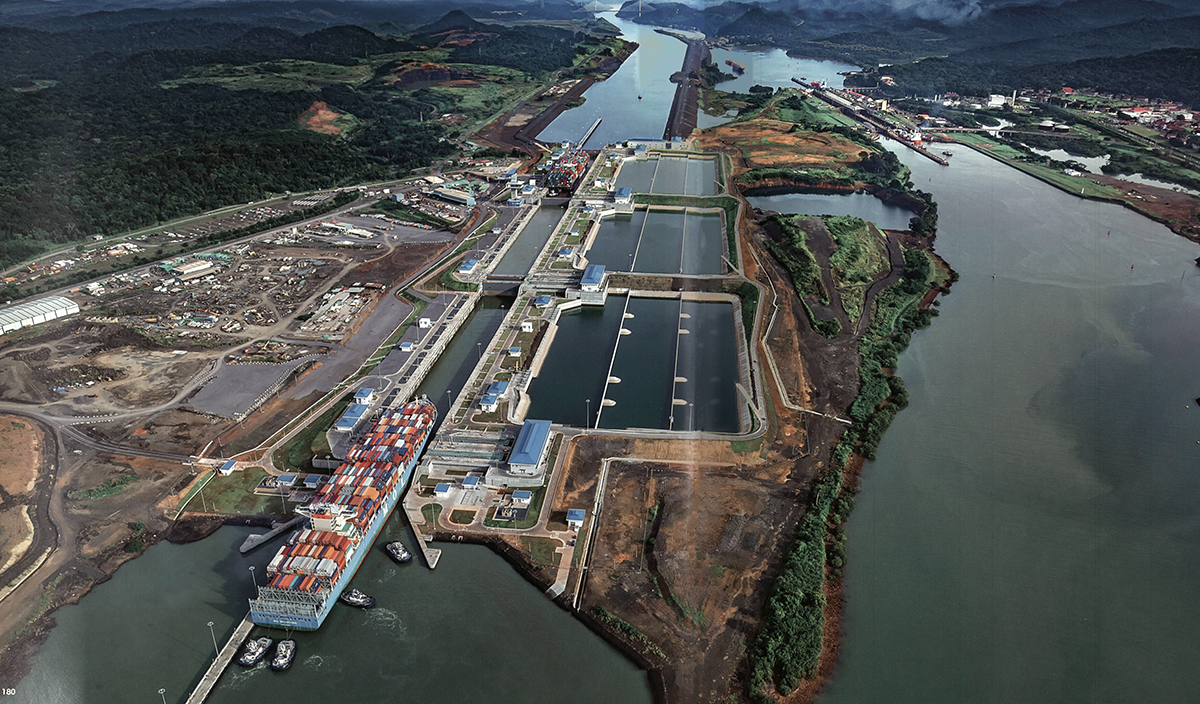
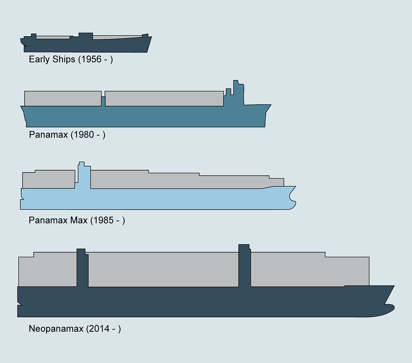
In 1999 the U.S. officially transferred control of the Panama Canal to the Republic of Panama. In 2016, the Panama Canal Authority (Autoridad del Canal de Panamá, ACP) opened two new sets of locks, adding to the original Panama Canal system. For decades, the maximum ship size that the Panama Canal could accommodate, a Panamax ship, influenced the dimensions of ship building. For many in the industry, the loss of revenue due to the limits of cargo capacity began to outweigh the value of utilizing the Canal as a shortcut. The new locks significantly expanded the size of ships that the Canal can accommodate. The term used to describe the largest ship that can fit through the new locks is Neopanamax.
ACP is investing in sustainability and making great efforts to reduce the impact of the Canal on the global environment and surrounding ecosystem. The new locks utilize a system of retaining basins that reuse 60% of the water.
Photo of New Locks from Omar Jaén Suárez’s El Canal de Panamá, 2018. Ediciones Balboa: Ediciones San Marcos. F1569.C2 J34 2018. Latin American and Caribbean Collection, George A. Smathers Libraries, University of Florida.
Ella Terran (designer), Panama Canal Ship Sizes, 2023.
Historical Film of the Construction of the Panama Canal, 1913-1914. U.S. National Archives and Records Administration. NAID: 24668, ID: 111-H-1163
Watch the video below to learn more about how the Panama Canal locks work.
Curated by Elizabeth Bemis
Online Exhibit Designed by Katiana Bagué
Exhibit Title designed by Ella Terran
This online exhibit is based on the exhibit of the same name that was on display at the Albert H. Nahmad Panama Canal Gallery from April 21, 2023, to March 29, 2024. Unless otherwise noted, all items are from the Panama Canal Museum Collection, Special & Area Studies Collections, George A. Smathers Libraries, University of Florida.